3.3.2. CN5000 Switch Installation
This section provides the requirements and instructions for installing the CN5000 Omni-Path Switch.
3.3.2.1. Unpacking the CN5000 Switch
Before unpacking, check for any obvious damage to the packaging. If any damage to the packaging or the contents is found, notify the reseller immediately.
3.3.2.1.1. Verify CN5000 Switch Package Contents
Ensure the CN5000 Switch package contents match the packing list.
3.3.2.1.2. Visually Inspect the CN5000 Switch
Check the switch for visual damage and then return the switch to its container until it is ready to install. If damage is noted or suspected, do not install the switch. Contact Cornelis Technical Support or your reseller for assistance.
Never attempt to install or use a damaged switch.
3.3.2.1.3. Tools Required
Tools required for this installation include the following:
An ESD wrist strap or other personal grounding device
Torque driver
A #1 and #2 Phillips screwdriver
Tip
Because DHCP is enabled on the switch by default and you have access to the MAC address on the switch label, Cornelis recommends that you add the MAC address of the switch to the DHCP server at this time.
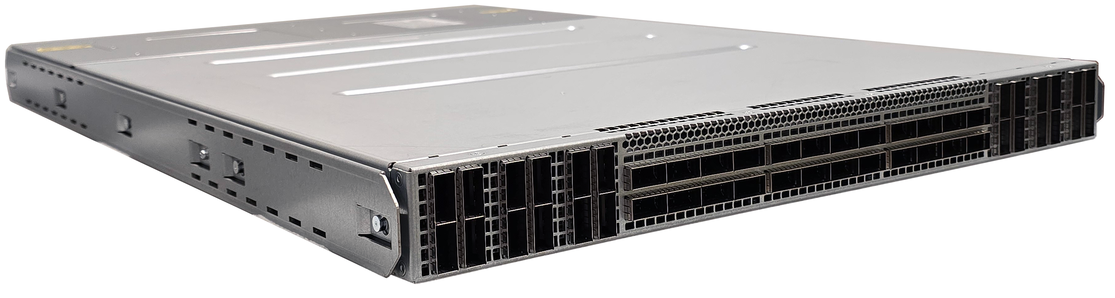
3.3.2.2. Installing the CN5000 Switch
This section outlines the steps necessary to install the CN5000 Switch. The following instructions apply to both air-cooled and liquid-cooled Switches, except where specifically noted.
3.3.2.2.1. Mark the Rack
Allow enough vertical space in the rack for each specific switch installation.
Determine the location in the rack for the bottom of the switch.
Mark the upper (if applicable) and lower mounting positions on the vertical rails on the front of the rack.
Mark the upper (if applicable) and lower mounting positions on the vertical rails on the back of the rack.
3.3.2.2.2. Install the Mounting Rails
To install the CN5000 Switch rail kit, perform the following:
For the first rail, insert the rail installation pin into the rack hole.
This holds the rail in place while the power supply side screws can be installed.
Figure 31. Rail Installation Pin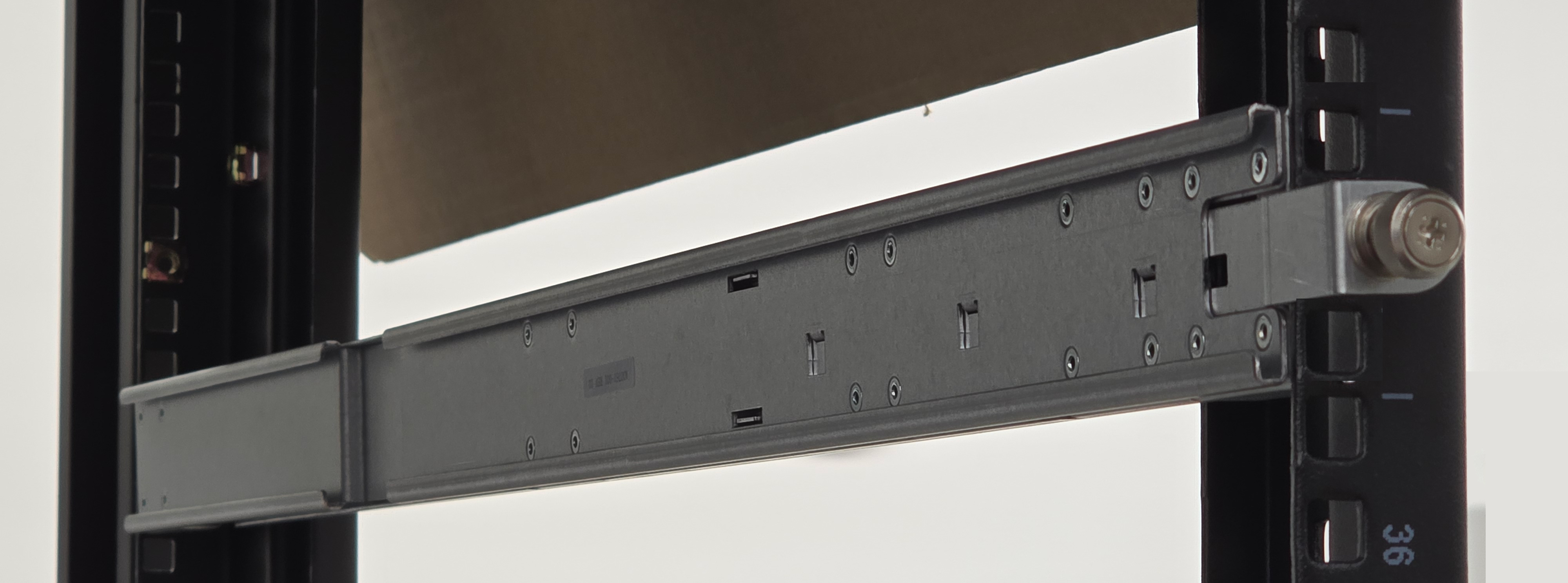
Fasten the rail to the power supply side using two M6 screws.
Figure 32. Secure the Power Supply Side of Rail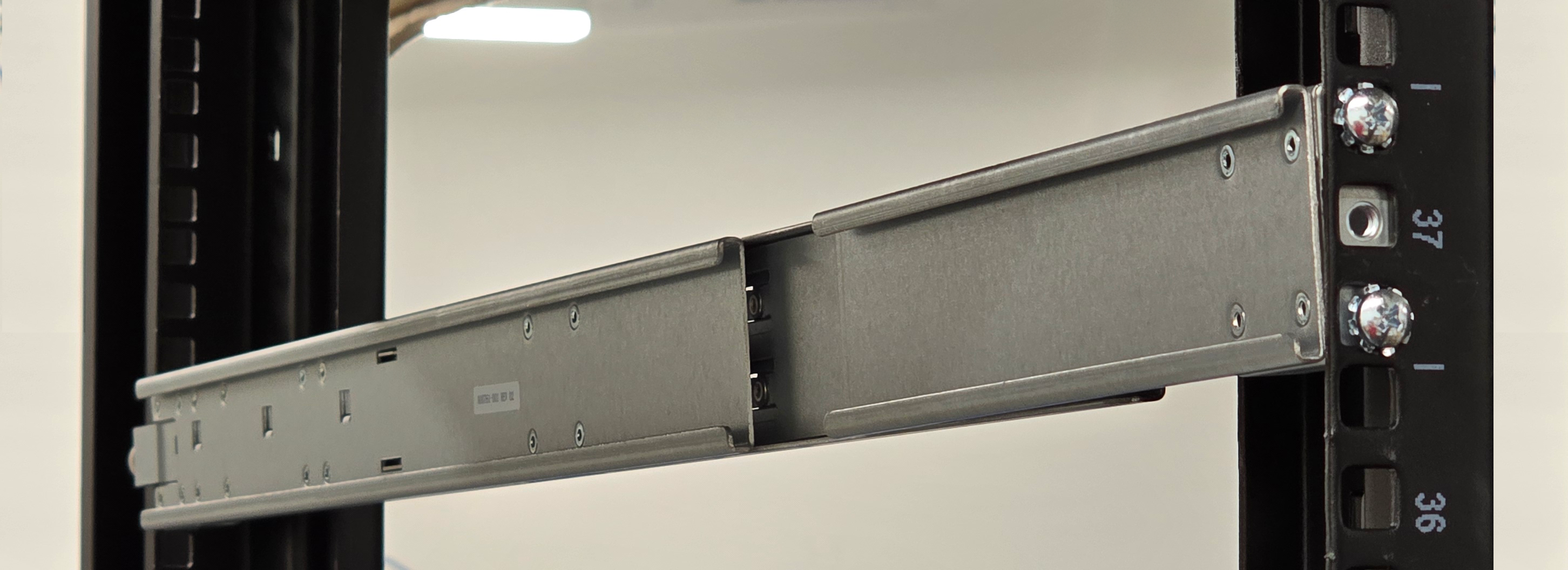
Use the torque driver to tighten the screws.
Repeat Steps 1-3 for the second rail.
Secure the port side of each rail using two M6 screws.
Figure 33. Secure Port Side Rail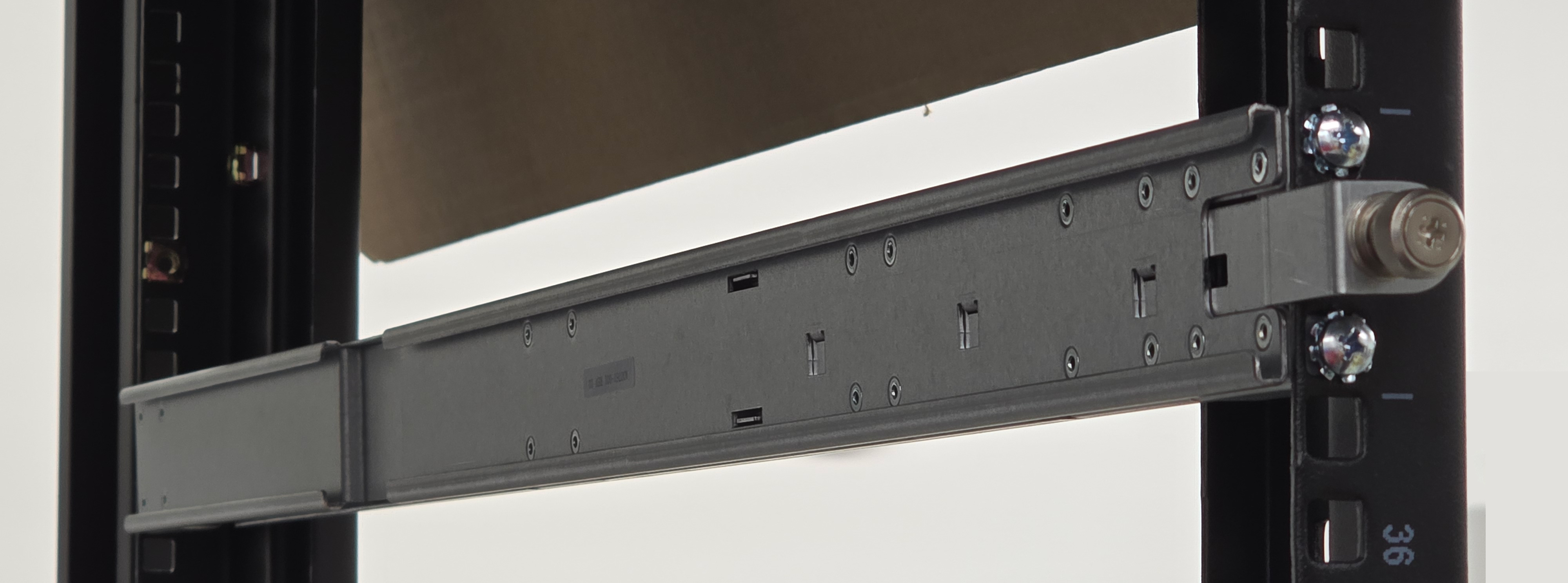
Use the torque driver to tighten all screws.
3.3.2.2.3. Install the CN5000 Switch into the Rack
To install the CN5000 Switch, perform the following:
Pull out the locking latches on both sides of the rack before installing the switch.
Figure 34. Extended Locking Latch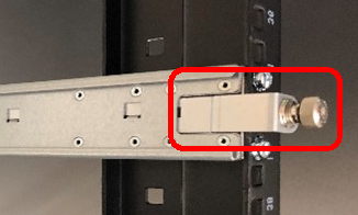
Slide the CN5000 Switch onto the rails.
Figure 35. Switch Mounted in a Four Post Standard Rack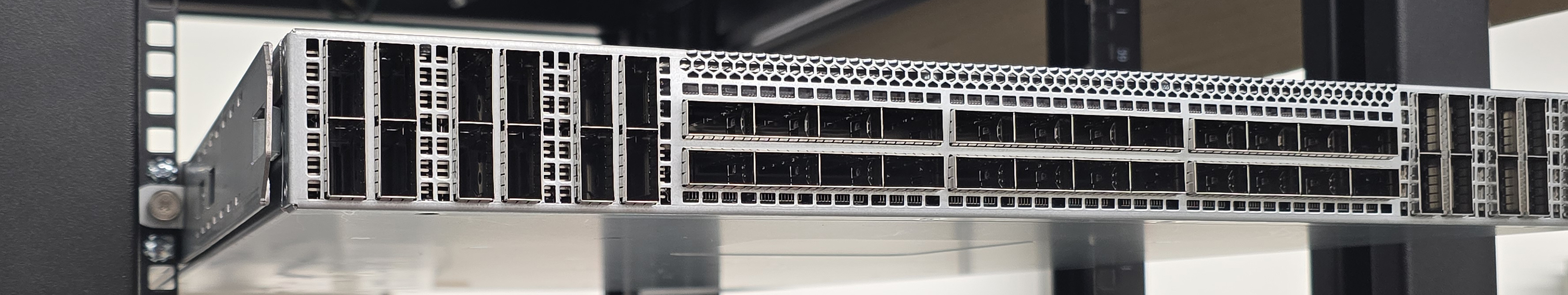
Insert the switch until it is fully inserted into the inner mounting rail tracks.
Figure 36. Switch Fully Inserted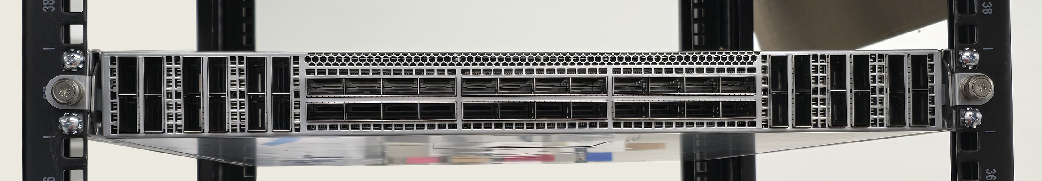
Slide the switch to the desired depth in the rack.
Figure 37. Switch Adjusted to Desired Depth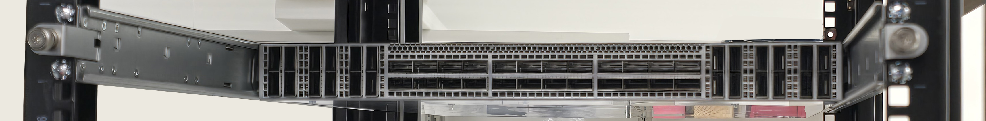
When the switch is at the proper depth, push in the locking latch and tighten the thumb screw.
3.3.2.2.4. Fill and Connect the Liquid-Cooled Switch
Note
CN5000 Switches are purged of liquid and then filled with nitrogen before shipping. This allows the customer to choose which working fluid to use (deionized water with additives, Propylene Glycol, or Ethylene Glycol). The quick disconnects (QDs) are Staubli SCG06UQD04 and are color-coded to indicate flow direction.
After the switch is installed in the rack, perform the following:
Purge the CN5000 Switch of nitrogen and fill with the desired working coolant (deionized water with additives, Propylene Glycol, or Ethylene Glycol).
Connect the color-coded (red/outlet and blue/inlet) QDs from the manifold to the Switch.
Note
Integrators will need to supply their own connections from the Switch to the cooling infrastructure.
Figure 38. Switch Liquid-Cooled Connections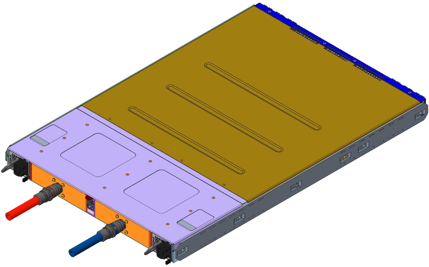
3.3.2.2.5. Connect the Power Cord
Insert the power cord into the power inlet until it clicks into place.
Figure 39. Inserting the Power Cord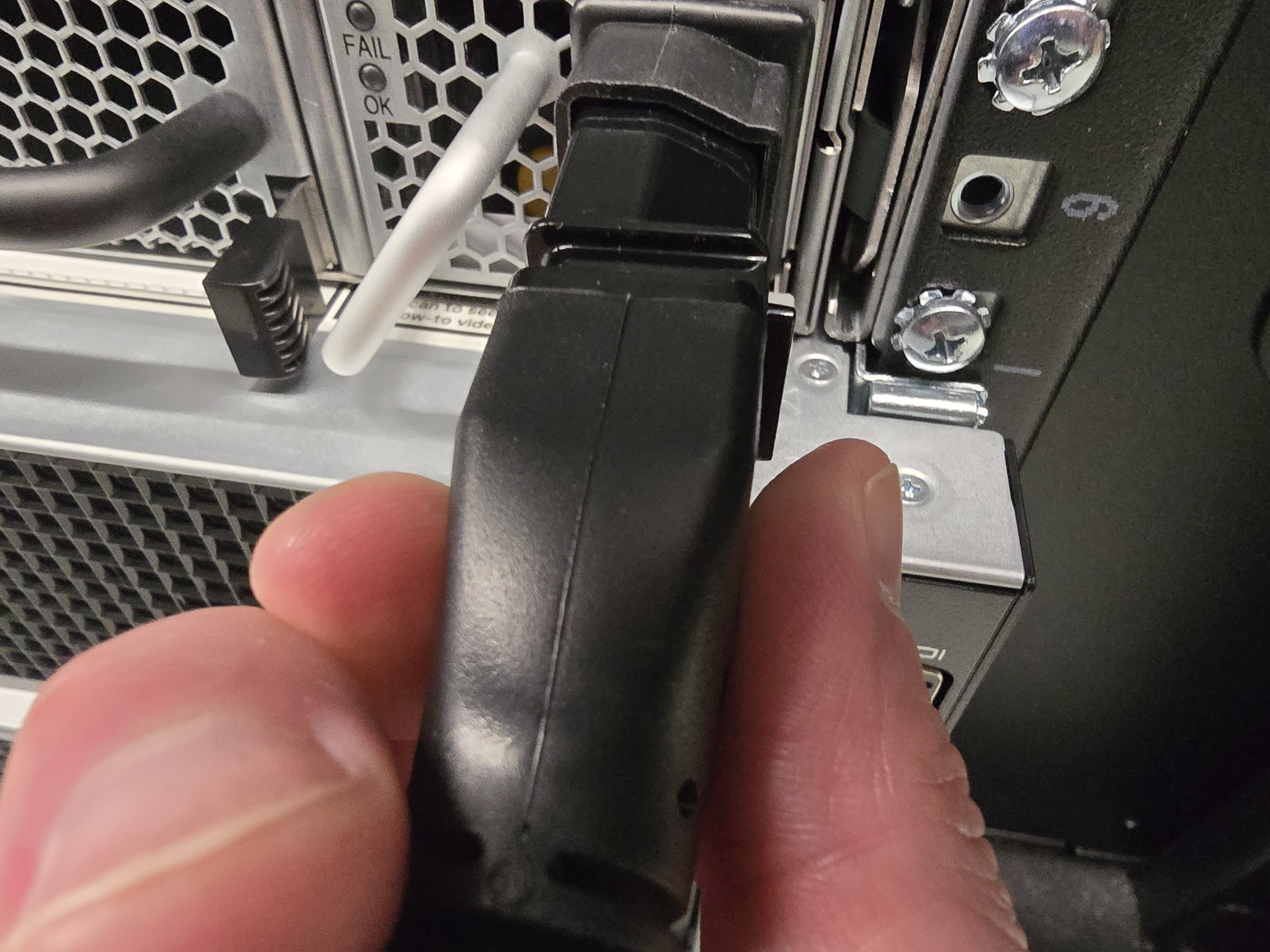
Note
If you need to remove the cord, press the release tab on the right of the plug and pull.
3.3.2.3. Cabling the CN5000 Switch
This section provides information for cabling port connections.
Caution
It is important to provide strain relief for the QSFP cable connector.
Using the ports on the front of the switch, connect the switch to the host(s) or switch(es) using QSFP cables.
Refer to your cable planning spreadsheet as described in Fabric Design Prerequisites.
Important
Before configuring the speed of a switch port, ensure that the attached cable supports the speed by using the Switch CLI command hardware cable. Refer to hardware and port.
3.3.2.3.1. CN5000 Switch to CN5000 Switch Cable Support
The cable lengths supported for CN5000 Switch to CN5000 Switch port pairs are summarized below.
DAC: up to 1.5 m
ACC: up to 4.0 m
AOC: up to 100.0 m
Contact Cornelis Technical Support for details on supported cable length on a per port basis.
3.3.2.3.2. Cabling for Port Subdivision
Port subdivision is automatically enabled for those ports shown in green in the following figure.
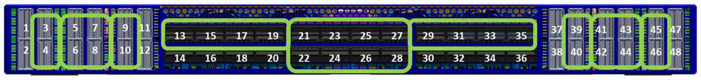
Plug the single end of a splitter 'Y' cable into a supported port and the other two ends into a SuperNIC. The Fabric Manager will automatically assign LIDs and show the links as subdivided two-lane links. Use opareport to view the connections.