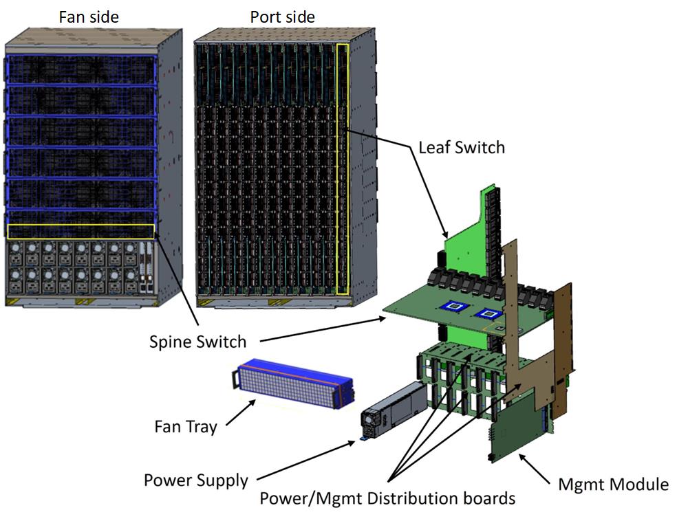
2.3.3. Director Class Switch
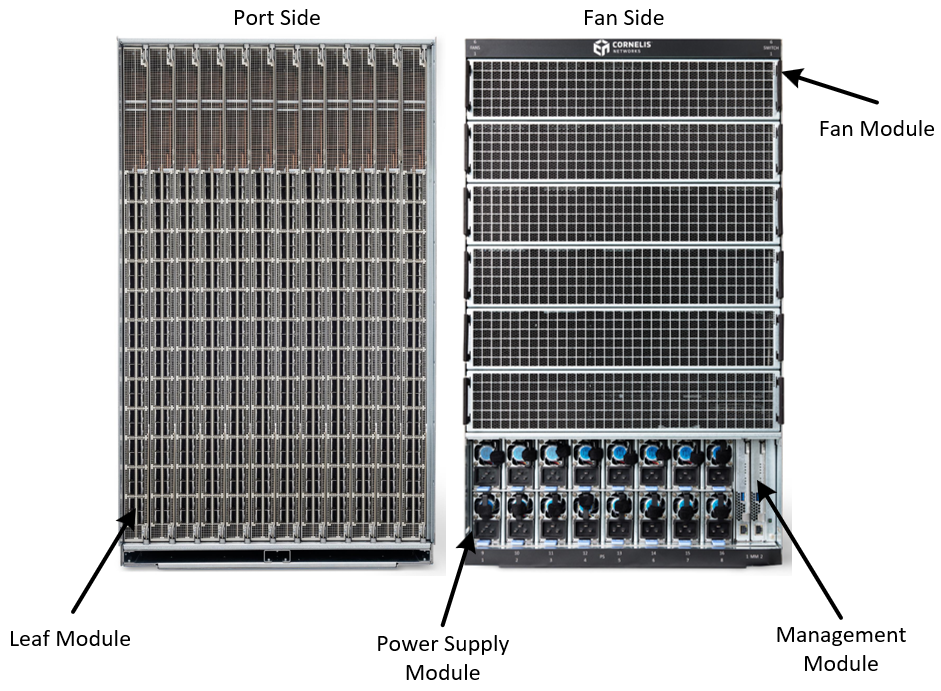
The Director Class Switch (DCS) Chassis is a high-density switching platform designed for enterprise and data center environments. The system is available in two cooling configurations: an 18U air-cooled version for standard deployments, or a 20U liquid-cooled variant for environments requiring enhanced thermal management. Both configurations are designed to fit standard 19-inch rack mount installations. The chassis provides 576 ports, each capable of 400 Gbps throughput.
The modular architecture supports up to 12 vertical Leaf Modules, with each module providing 48 ports at 400 Gbps for external fabric connectivity. These Leaf Modules work in conjunction with six horizontal Spine Modules that are required for the internal switching fabric, creating a robust two-tier fat-tree topology. The base configuration comes fully equipped with all essential infrastructure components, including the Field Replaceable Unit (FRU) chassis, N+1 redundant power supply modules for high availability, all necessary fan tray modules for proper cooling, and all management modules required for system administration and monitoring.
The DCS supports both copper and optical cables and operates at full bandwidth with optical cables up to 50 meters and at half bandwidth with 100-meter optical cables.
Each of the DCS components are hot pluggable common components of the chassis, giving customers the flexibility to deploy and grow AI and HPC environments in a cost-effective manner. In addition, the orthogonal interconnect architecture, with Leaf and Spine Modules connected directly, eliminates the need for a backplane.
Note
The CN5000 Director Class Switch is interoperable with the Cornelis Omni-Path Express 100 Series (OPA100) Edge Switch, Director Class Switch, and Host Fabric Interface adapter. In these cases, the links will operate at 100 Gbps total bandwidth (25 Gbps per lane).
When connecting OPA100 devices to a CN5000 fabric, the Fabric Manager must be located on a CN5000 host.
2.3.3.1. Leaf Module
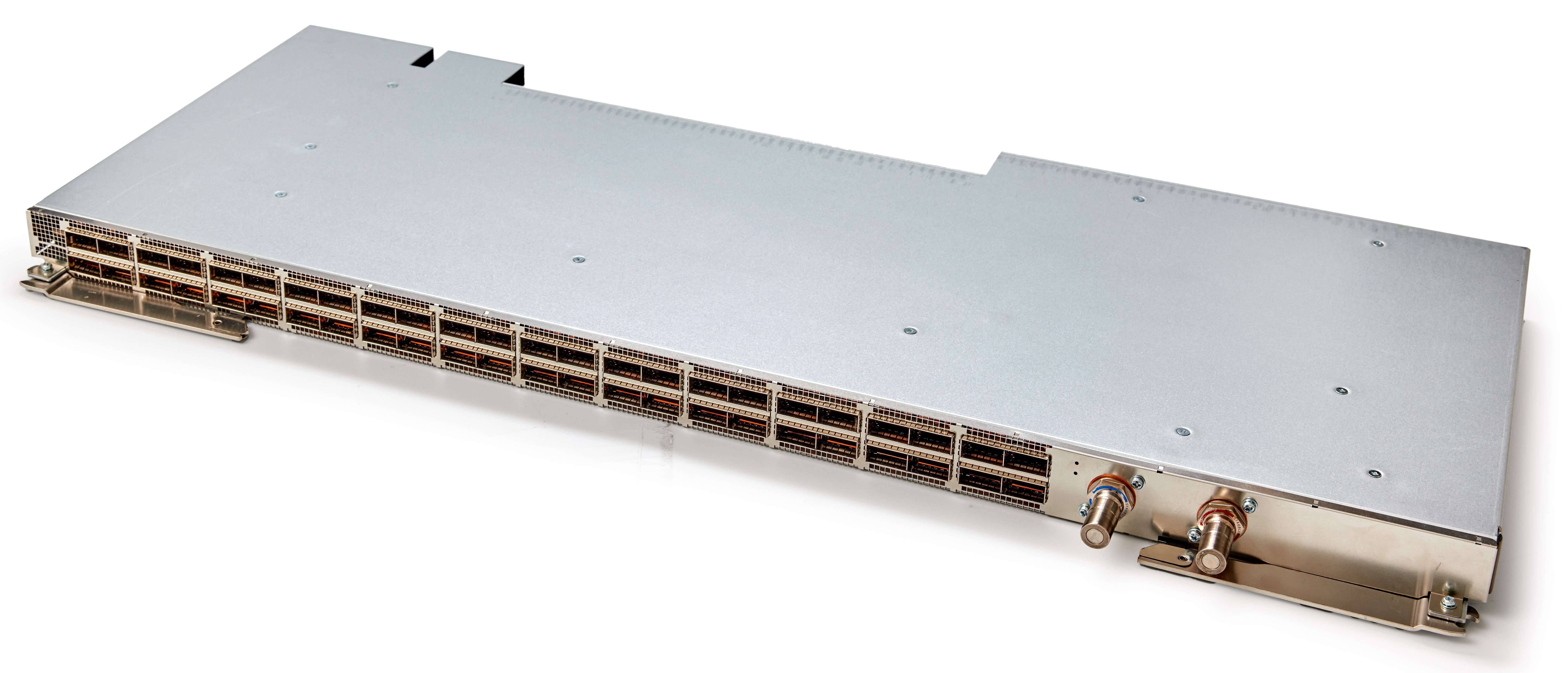
The Leaf Module is a hot-swappable network component that provides high-density connectivity with 48 QSFP112 user ports, each capable of 400 Gbps throughput. In addition to the user-facing ports, the module features 48 internal 400 Gbps system ports that connect within the chassis infrastructure, enabling robust internal communication and data flow.
The Leaf Module is available in both air-cooled and liquid-cooled configurations (shown in the following figures) to accommodate different thermal management requirements. The liquid-cooled variant employs direct liquid cooling technology that targets critical heat-generating components, including the ASIC, QSFP ports, and voltage regulators, providing efficient thermal dissipation for high-performance environments.
Note
It is important to note that air-cooled and liquid-cooled Leaf Modules cannot be mixed within the same chassis.
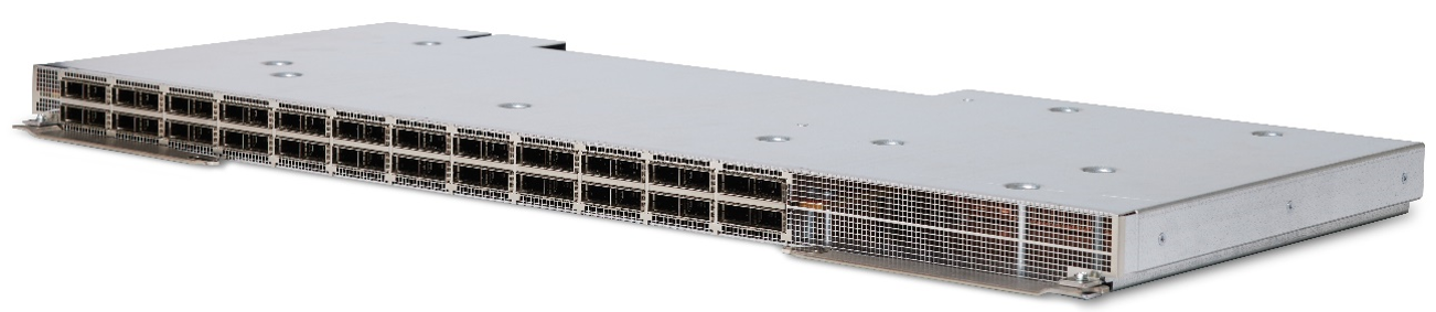
The following figure shows the leaf module port numbering where the bottom of the leaf module is on the left.

The leaf module is vertically oriented in the chassis. Port 1 is located at the bottom, left of the leaf module when facing the chassis.
The Leaf Module provides Tier-1 switching for the DCS with user port and system port interconnect to the Spine Module. The Leaf Module also provides sub-system management for control and telemetry. The DCS supports up to 12 Leaf Modules. At least one Leaf Module should be installed for the operation of the Switch.
For LED information, refer to Leaf Module LEDs.
2.3.3.2. Spine Module
The Spine Module is designed as a hot-swappable component that features 96 high-performance 400 Gbps ports configured as 4x system ports, which are internal to the chassis. This module offers flexibility in thermal management with both air-cooled and liquid-cooled options available to meet different data center requirements.
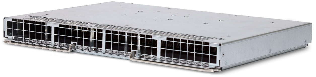
The liquid-cooled variant employs direct liquid cooling technology that specifically targets the ASIC and voltage regulators for optimal thermal performance.
Note
It is important to note that air-cooled and liquid-cooled Spine Modules cannot be mixed within the same chassis.
The Spine Modules (shown in the following figures) deliver Tier-2 switching for the DCS, connecting system ports to the Leaf Modules. They also manage control and telemetry for the subsystem. The DCS supports up to six Spine Modules. The Spine Module LEDs are located on the Fan Tray Module.
For LED information, refer to Fan Tray and Spine Module LEDs.
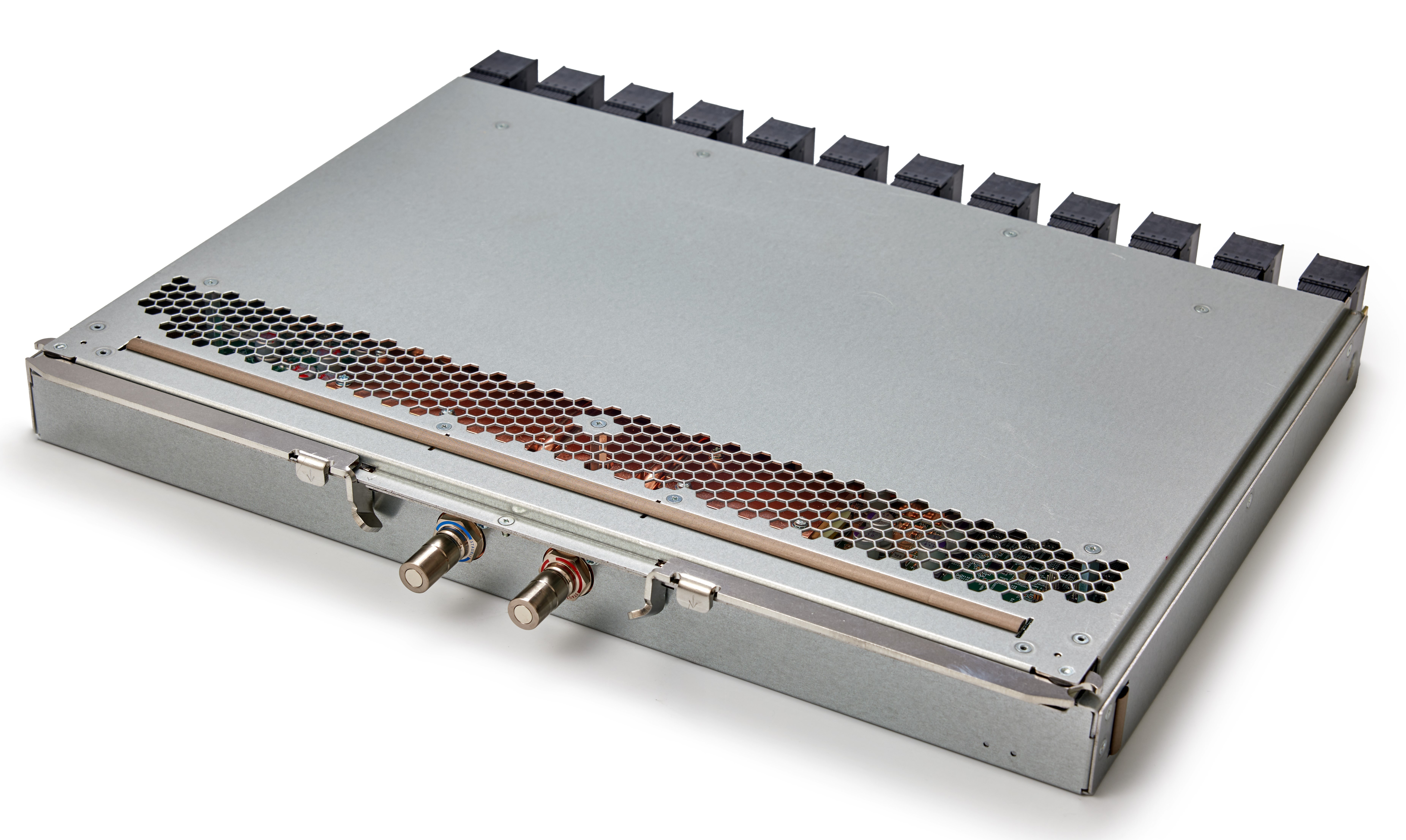
2.3.3.3. Management Module
The Management Module provides robust chassis management capabilities with enterprise-grade reliability features. The module is designed to be hot swappable, allowing for maintenance and replacement without system downtime, ensuring continuous operation of critical infrastructure. It operates in a 1+1 redundancy configuration, providing failover protection through dual module deployment to eliminate single points of failure and maximize system availability.
 |
The Management Module uses BMC-based chassis management that embraces open standards for maximum flexibility and interoperability. It supports OpenBMC and Redfish capabilities, enabling standardized approaches for system installation, configuration, and ongoing monitoring. The BMC-based management supports out-of-band monitoring and management of the Leaf, Spine, Fan Tray Modules and Power supplies. The DCS supports up to two Management Modules.
For LED information, refer to Management Module LEDs.
2.3.3.4. Chassis EEPROM Board
The Chassis EEPROM Board (CEB) contains a non-volatile I2C EEPROM memory chip that stores essential Vital Product Data including the chassis GUID, manufacturer information, serial numbers, slot configuration details, and other chassis-specific parameters that are programmed during manufacturing and accessed by management firmware during system operation for identification, inventory management, and configuration purposes.
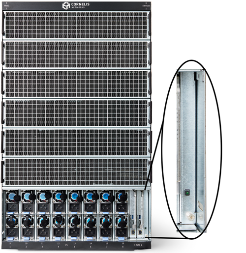
The CEB incorporates a physical 54 V on/off power switch for the DCS platform, providing manual power control capability. The power button displays a green LED when on.
The CEB is neither hot-swappable nor field-replaceable.
2.3.3.5. Power Supply Module
The Power Supply Module is designed for high-availability operations with hot-swappable functionality, allowing for module replacement without system shutdown when operating with greater than the minimum number of required supplies. This feature ensures continuous system operation during maintenance or replacement procedures, minimizing downtime in critical environments.
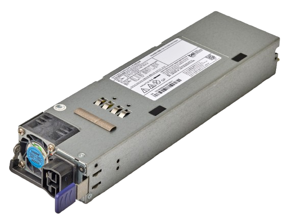
The module operates with a wide input power range of 200–277 VAC at 50–60 Hz, providing flexibility for deployment across various international power standards and infrastructure requirements. Each supply unit delivers a maximum output rating of 3500 watts, providing substantial power capacity for demanding applications. For reliable and safe power connectivity, the module utilizes an Anderson Power Products Saf-D-Grid 400 connector for its input power interface, ensuring secure and standardized power connections suitable for high-current applications.
The power supply module provides 3.5 kW, 54 VDC output power. The DCS requires a minimum of eight power supplies for normal operation, nine for N+1 (DC) redundancy, and 16 for N+N (AC) redundancy.
For LED information, refer to Power Supply Modules LEDs.
2.3.3.6. Fan Tray Module
The Fan Tray Module provides primary cooling for the air-cooled variant and stray heat extraction in the liquid-cooled variant. Each Fan Tray Module consists of five fans per module and is oriented to provide airflow in the Port-to-Fan direction only. The DCS requires all six Fan Tray Modules to be populated for air cooling. Only one fan tray module is required for liquid cooling, which is in slot F206 of the DCS.
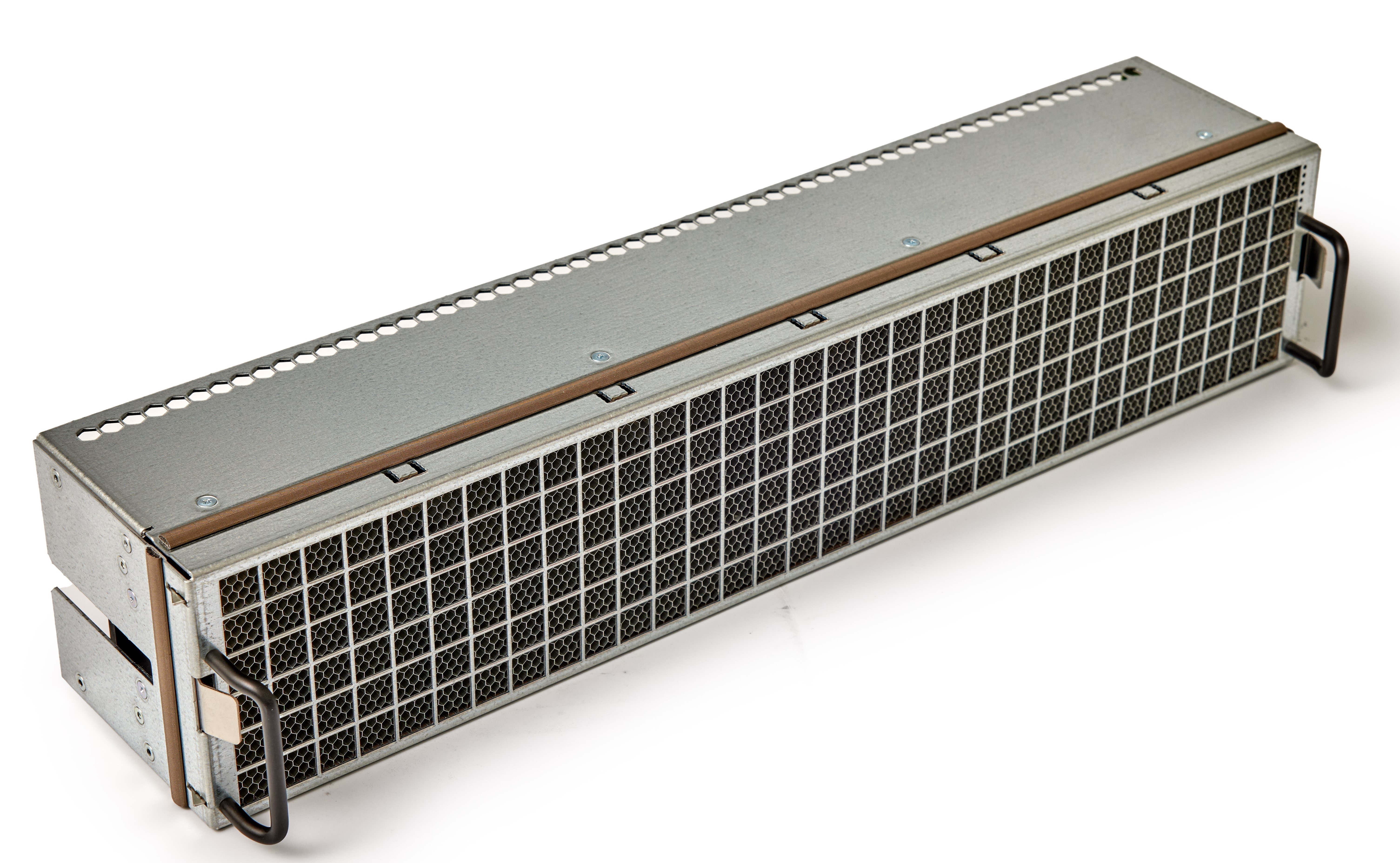
The Fan Tray Module is designed with hot-swappable capability, allowing for replacement or maintenance without system shutdown, which ensures continuous operation and minimal downtime. The module features variable speed control, enabling the fans to adjust their cooling performance based on system thermal requirements, optimizing both cooling efficiency and power consumption.
The system includes six Fan Tray Modules with distinct functional configurations. Fan Tray Modules 1, 2, and 3 are positioned in front of Spine modules and provide LED indicators for these associated Spine modules, offering visual status information for monitoring and diagnostics. In contrast, Fan Tray Modules 4, 5, and 6 are not positioned in front of any Spine modules and therefore do not provide any LED indications, as they lack the associated hardware components to monitor.
For LED information, refer to Fan Tray and Spine Module LEDs.
2.3.3.7. DCS Feature Summary
The Director Class Switch represents a state-of-the-art communication infrastructure designed to meet the demanding requirements of medium to large switching environments, delivering exceptional performance, scalability, and reliability through advanced packaging technologies and comprehensive feature sets. Key features include the following:
576 ports configured in 48-port increments, each delivering 400 Gbps performance
Scales up to 230.4 Tbps total system bandwidth
Two-tier fat tree topology for optimal traffic distribution
Optimized architecture for superior message rates
Engineered for maximum uptime with module redundancy
Redundant out-of-band management for continuous system oversight
2.3.3.7.1. Management
In-band and out-of-band management options to accommodate diverse network architectures and security requirements
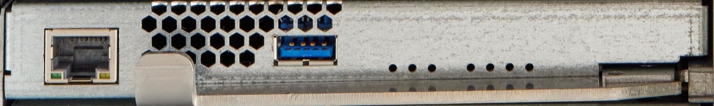
Command line interface through 10/100/1000 BASE-T Ethernet: Enables direct network-based interaction for configuration and monitoring tasks
USB serial port for direct console access and emergency management scenarios
Integrated NTP support ensures accurate time synchronization across the management infrastructure
Lightweight Directory Access Protocol (LDAP) for centralized authentication and user management
2.3.3.8. DCS Physical Specifications
2.3.3.8.1. DCS Chassis Specification
Feature | Air-Cooled | Liquid-Cooled |
|---|---|---|
400 Gbps port increment (minimum) | 48 | |
400 Gbps port total (maximum) | 576 | |
Total System Bandwidth (bidirectional) | 57.6 TBps | |
Chassis Height (+ Support Tray) | 18U | 20U |
Dimensions (W x H x D) [in (cm)] | 17.6 x 31.5 x 29.0 (44.7 x 80.0 x 73.7) | 17.6 x 35.0 x 29.0 (44.7 x 88.9 x 73.7) |
Weight (Empty FRU Chassis) | 163 lb (74 kg) | 206 lb (93 kg) |
Weight (Base 1N: All Fans, both Management Modules, N+1 PSUs) | 306 lb (139 kg) | 320 lb (145 kg) |
Weight (fully configured, N+1 PSUs) | 630 lb (286 kg) | 673 lb (305 kg) |
Packaged Dimensions (W x H x D) [in (cm)] | 36.0 x 44.0 x 40.0 (91.4 x 111.8 x 101.6) | 36.0 x 44.0 x 40.0 (91.4 x 111.8 x 101.6) |
Packaged Weight (fully configured/palletized, N+N PSUs) | 705 lb (320 kg) | 768 lb (348 kg) |
Leaf Modules (maximum) | 12 | |
Spine Modules (maximum) | 6 | |
Fan Modules | 6 | 1 |
Management Modules | 2 | |
Power Supplies (minimum/DC/AC redundancy) | 8 / 9 / 16 | |
Power (kW AC, typical1) with DSP optics | 21.9 | 21.1 |
Power (kW AC, maximum2) with DSP optics | 23.6 | 22.5 |
Cooling (maximum required) | 2460 CFM at 40 °C | 410 CFM at 40 °C |
NOTES:
| ||
2.3.3.8.2. Module Specifications
Module | Dimensions (W x H x D) [in (cm)] | Weight [lb (kg)] |
|---|---|---|
48P Leaf Module, Air-Cooled | 11.66 x 1.38 x 27.88 (29.62 x 3.51 x 70.82) | 20.8 (9.4) |
48P Leaf Module, Liquid-Cooled | 12.1 x 1.38 x 27.88 (30.73 x 3.51 x 70.82) | 21 (9.5) |
Spine Module, Air-Cooled | 17.15 x 1.71 x 13.55 (43.56 x 4.34 x 34.42) | 15.6 (7.1) |
Spine Module, Liquid-Cooled | 17.15 x 1.71 x 14.23 (43.56 x 4.34 x 36.14) | 15.0 (6.8) |
Fan Tray Module | 17.37 x 3.46 x 4.56 (44.12 x 8.79 x 11.58) | 5.8 (2.6) |
Power Supply Module | 2.89 x 1.54 x 12.13 (7.34 x 3.91 x 30.81) | 3.0 (1.36) |
Management Module | 0.79 x 5.94 x 11.63 (2.0 x 15.09 x 29.54) | 1.6 (0.7) |
NOTES:
| ||
2.3.3.9. DCS LEDs
The Director Class Switch LED indicators serve as visual status and diagnostic tools for monitoring the health and operational state of the chassis and its components.
NOTE: Spine Modules are located internally behind the Fan Tray modules.
2.3.3.9.1. Management Module LEDs
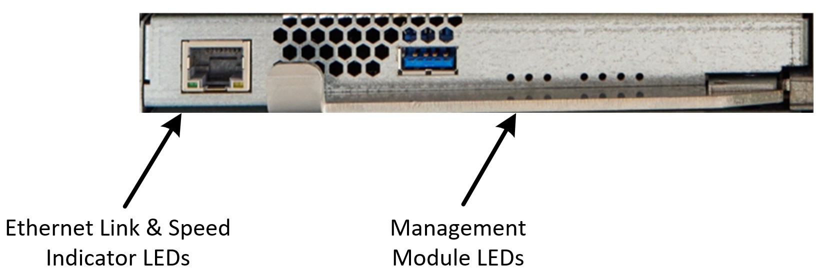
2.3.3.9.1.1. Ethernet Link and Speed Indicator LEDs
The Ethernet link LED (left, orange) provides the following indications:
Off – No Link
On – Link
The Ethernet link speed LED (right, yellow) provides the following indications:
Solid On – No Activity
Blink – Activity
2.3.3.9.1.2. Management Module LEDs
The management module indications from left to right are:
Primary – On: Management Unit in Control
Chassis Service
Chassis Fault Tolerant
Chassis Attention
Chassis Status
Module Attention
Module Status
2.3.3.9.2. Leaf Module LEDs
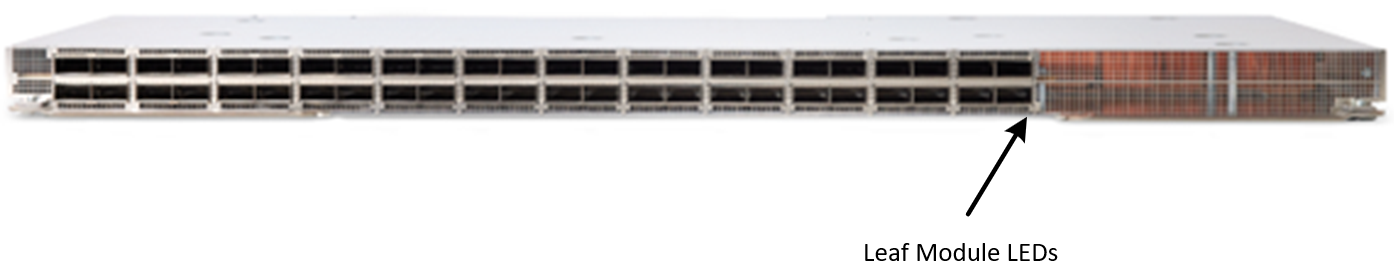
2.3.3.9.2.1. Module Status
When on, the module Status LED (green) indicates the module is powered and good.
2.3.3.9.2.2. Module Attention
When blinking, the module Attention LED (amber) indicates a fault.
2.3.3.9.3. Fan Tray and Spine Module LEDs
Each fan module includes six LEDs in the upper right corner.
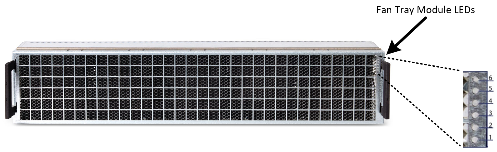
The Fan Tray Module LEDs provide indications for the Fan Tray and Spine modules and are assigned, top to bottom in the chassis, as noted in the following table.
Fan Tray Module | Lower Spine | Upper Spine |
|---|---|---|
6 | ‒ | ‒ |
5 | ‒ | ‒ |
4 | ‒ | ‒ |
3 | 5 | 6 |
2 | 3 | 4 |
1 | 1 | 2 |
Note
In an air-only configuration, only the LEDs in the bottom three fan tray modules are used.
The Fan Tray LEDs provide the indications shown in the following table.
LED | Description | Condition |
|---|---|---|
1 | Upper Spine Status (green) On | Powered |
2 | Upper Spine Attention (yellow) On | Not ready |
3 | Fan Status | Refer to following table |
4 | Fan Attention | Refer to following table |
5 | Lower Spine Status (green) On | Powered |
6 | Lower Spine Attention (yellow) On | Not ready |
The Fan Tray Module Status and Attention LEDs provide the indications shown in the following table.
Fan Status (Green) | Fan Attention (Amber) | Condition |
|---|---|---|
On | On | System start-up, 80% of full speed |
On | Off | All fans present and operating |
On | Blink | Single fan failure |
Off | On | Fan tray failure |
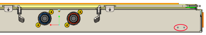
2.3.3.9.3.1. Liquid-Cooled Fan Tray LEDs
The liquid-cooled module will have two LEDs on the bottom right. Left is status (Green = ON) and right is attention (Amber).
2.3.3.9.4. Power Supply Modules LEDs
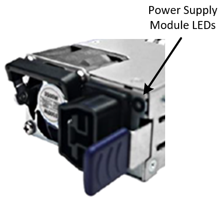
The Power Supply Module LED is a bicolored (green/amber) indicator providing the following indications:
Green, On steady – Good
Off – No AC power to all power supplies
Green, 1 Hz blink – Standby
Amber, On steady – AC power lost/unplugged OR critical shutdown event
Amber, 1 Hz blink – Warning events with power supply operating
Green, 2 Hz blink – Firmware updating