5.2.2. vFabric Overview
A vFabric consists of a group of applications that run on a group of devices. For each vFabric, the operational parameters of the vFabric can be selected.
As shown in the following figure, the virtual fabrics definition involves defining a set of applications, device groups, and virtual fabrics. Each application is defined as a set of ServiceIDs and/or Multicast Group IDs (MGIDs). These are defined in terms of pattern match rules (or explicit lists) so that the wide range of 64- and 128-bit inputs can be easily specified.
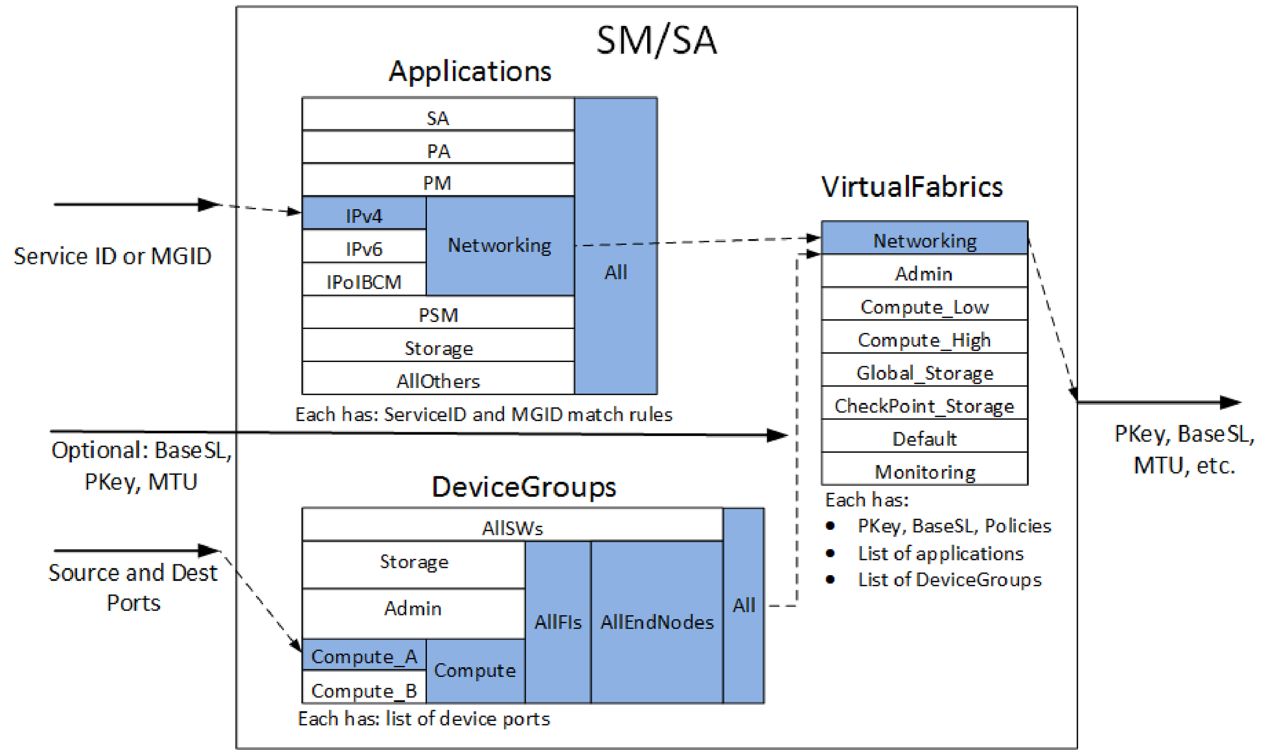
Applications may also contain lists of other applications. This can permit the definition of higher-level applications (such as Networking, shown in the figure) to reuse existing definitions for lower-level applications (such as IPv4, IPv6, and IPoIB-CM, as shown in the figure).
Each DeviceGroup consists of a list of device ports. Those device ports may be explicitly listed or matched via Node Description pattern matching. DeviceGroups may also contain lists of other DeviceGroups. This can permit the definition of higher-level groups (such as Compute) to reuse existing definitions for lower-level groups (such as Compute_A and Compute_B).
Finally, a Virtual Fabric is defined as a list of applications, a list of device groups, with a set of QoS and security policies, along with the PKey and BaseSL identifiers for the VirtualFabric.
Within the Open Fabrics Alliance APIs, packets for a given virtual fabric are identified by a PKey (indicating security) and a BaseSL (indicating QoS). During fabric initialization, the FM will have configured the devices to be aware of these two identifiers and assign the appropriate security (for example, limited/full/none membership) and QoS (for example, MTU, bandwidth, priority, static rate, flow control, HoqLife) policies to these identifiers at each port in the fabric. The settings for these policies may also influence other parameters for the port such as how buffers, VLs, and other resources are allocated to each virtual fabric.
The virtual fabrics mechanisms are closely tied to address resolution and multicast membership in the Open Fabrics Alliance APIs and applications.
When an application makes an address resolution or multicast membership query to the FM, the FM checks the application identifier (ServiceID or Multicast Group ID (MGID)) against the FMs list of applications to identify one or more potential matches. It also checks the source and destination nodes against the FMs list of DeviceGroups to identify one or more potential matching device groups. The FM then looks for virtual fabrics. This search includes both a matching application and a matching device group that also matches any supplied BaseSL, PKey, and MTU. Then one or more resulting virtual fabrics are used to compose address resolution responses which include the PKey, BaseSL, and other communications parameters (MTU, StaticRate, PktLifeTime) which the application should use to communicate through the fabric to the identified destinations.
Additionally, Figure 76 shows an example of the resolution mechanism during address or multicast resolution by SM/SA.
In this example, a ServiceID (address resolution) or an MGID (multicast join/create) is supplied that matches the IPv4 Application. The IPv4 Application is part of the Networking and All applications, so they are also matched. A source and destination are supplied explicitly or implicitly, and a DeviceGroup is selected that matches both. In this example, the Compute_A group includes both the source and destination. The Compute_A group is also included in the Compute, AllFIs, AllEndNodes, and All groups, so they are also matched.
Note
Depending on the definition of Applications and DeviceGroups, it is possible for a given input to match two or more disjointed entries.
Given the list of matched Applications and matched DeviceGroups, the SM/SA searches the VirtualFabrics list for an entry that includes both a matched Applications and a matched DeviceGroups. In this example, the Networking VirtualFabric entry includes the Networking Application and the All DeviceGroup. If supplied, additional input parameters (BaseSL, MulticastSL, PKey, MTU) are also compared to the VirtualFabric entry to confirm a match. Finally, the response includes the PKey, BaseSL, MTU, and other relevant policies from the matched VirtualFabric.
For more information on how address resolution or multicast membership mechanisms in various applications can be integrated with virtual fabrics, see Fabric Manager Integrating Job Schedulers with Virtual Fabrics and Integrating Other Service Applications with vFabrics.
Example Configurations
Some concepts of virtual fabrics can be explained using simple configuration examples.
The following figure shows the default FM configuration of virtual fabrics, including a series of devices (compute nodes A, compute nodes B, storage, switch Port 0s, FMs, and other Admin nodes, such as job schedulers).
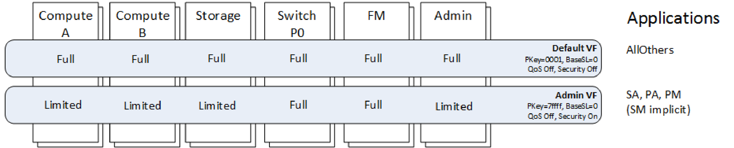
In a given cluster there may be many of each type of device. Horizontally, two virtual fabrics are shown - Default VF and Admin VF. For each of these virtual fabrics, a few of the key parameters are indicated: PKey, BaseSL, QoS on/off, and Security on/off. Parameters such as the PKey and BaseSL can be explicitly specified or dynamically assigned by the FM. On the far right are the Applications that are associated with each virtual fabric.
In this example, the Default virtual fabric consists of all devices and "All Others" applications (in the default opafm.xml file, AllOthers is defined as containing UnmatchedServiceID and UnmatchedGID; see Application Parameters for more information on UnmatchedServiceID and UnmatchedGID). This virtual fabric will be used by the majority of applications and is assigned a PKey 0x0001 and BaseSL 0.
The Admin virtual fabric is used for secure fabric management of the fabric (SA, PA, PM, and implicitly the SM). It includes all the FM nodes and all the switch port 0s (which may also manage devices inside their given switch chassis). All other nodes are limited members. This virtual fabric is assigned PKey 0x7fff and BaseSL 0.
In this configuration, all traffic shares a single BaseSL, so there is no fabric QoS. The Admin traffic is secured so that SA, PA, PM , and SM traffic is permitted only between the FM (and switch port 0s) and other devices. However, other devices, such as Compute A devices, cannot attempt to manage other devices in the fabric.
The following figure builds on the Default Virtual Fabrics Configuration by providing an additional Compute virtual fabric. The Compute vFabric includes all devices and the Compute applications. This virtual fabric uses PKey 0x0001 and BaseSL 1.
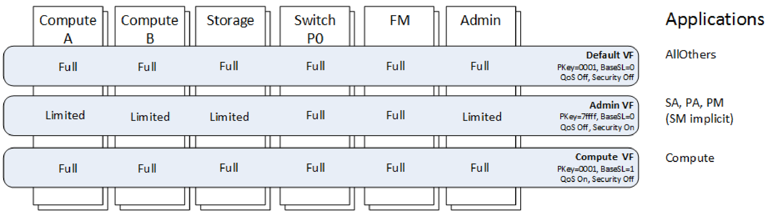
In this configuration, no new security is enabled. By assigning Compute to a unique BaseSL (and configuring the Compute vFabric's QoS policies), the Compute fabric's traffic can be separated from other fabric traffic by using a unique BaseSL and unique SCs and VLs throughout the fabric. This example also points out the flexibility and cross matching of vFabrics. The Default and Compute virtual fabrics share a common PKey and therefore have the same security rules. However, the Default and Admin virtual fabrics share a common BaseSL and therefore have the same QoS rules.
The following figure builds further on the Default Virtual Fabrics Configuration. In this figure, eight unique virtual fabrics are defined and each is assigned a unique BaseSL. This configuration has limited security as only management traffic is secured on PKey 0x7fff. All other traffic is unsecured and uses PKey 0x0001.
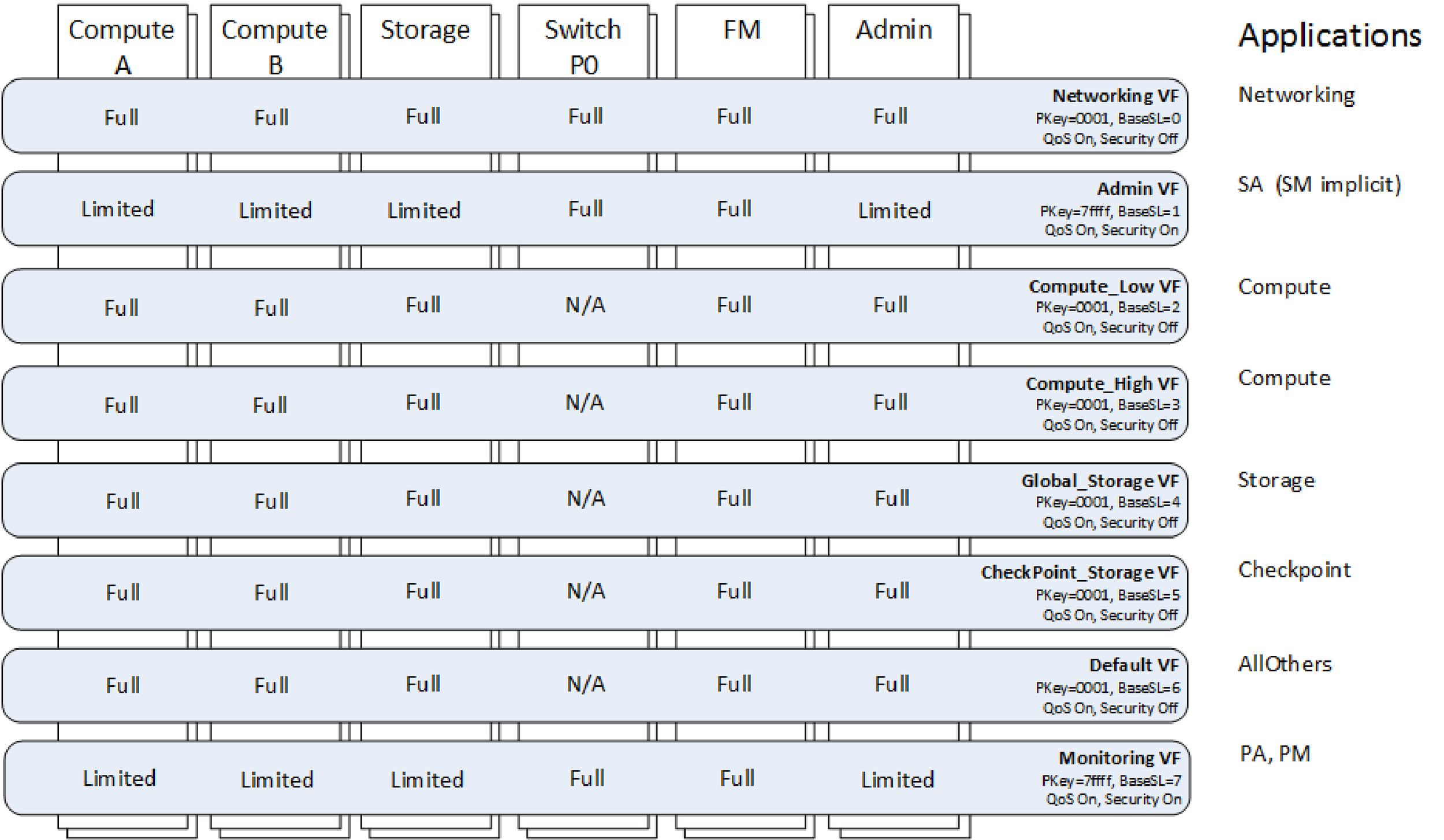
However, by assigning each virtual fabric a unique BaseSL, they each have unique QoS characteristics. The performance impacts between virtual fabrics will be controlled by the QoS policies configured for each virtual fabric. In this configuration, due to separate BaseSLs, SCs, and VLs per virtual fabric, the fabric performance statistics can also be monitored per virtual fabric. This occurs in the Performance Manager and is based on analysis of the per VL statistics on each port. This example also shows that, if desired, the management traffic can also be split out. In this example, the Admin virtual fabric is used for SA traffic while the Monitoring virtual fabric is used for PM and PA traffic. This can permit the PM traffic to proceed at regular intervals with less impact from bursty name resolution traffic that may be occurring to the SA.
The following figure is a security-focused example where each virtual fabric is assigned a unique PKey. The Compute A virtual fabric is limited to the Compute A devices. Similarly, the Compute B virtual fabric is limited to the Compute B devices.
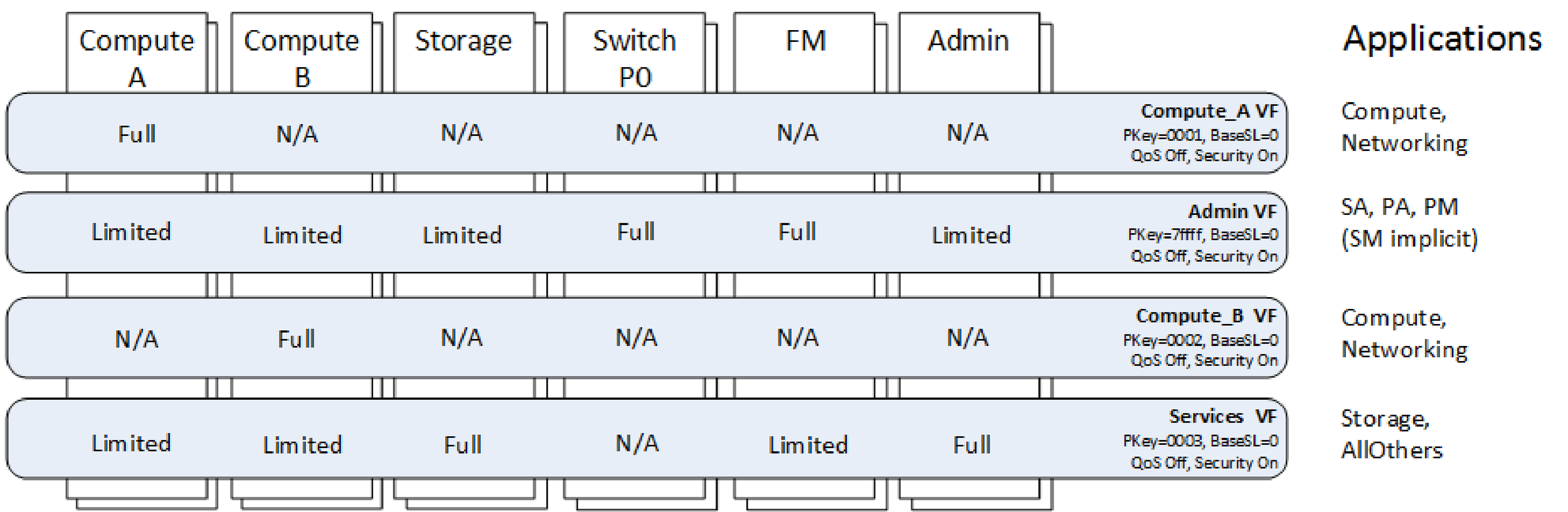
This means a compute application can only be run within the Compute A or the Compute B devices, but may not use devices from both groups. Both networking and Compute applications are permitted within those two virtual fabrics, so Compute A can be its own separate IP subnet from Compute B. This style of configuration may be useful when multiple departments or tenants of the cluster each need separate subsets of the cluster to run jobs and the sysadmin wants to secure the traffic so applications cannot mistakenly communicate with each other. This example also has an Admin virtual fabric, similar to the configuration in Figure 77 which secures the fabric management traffic from the other traffic. Finally, there is a Services virtual fabric that includes the storage and admin nodes as full members, with Storage, and other applications. This permits the storage and admin node to communicate with any node in the fabric, but it prevents the nodes in Compute A from attempting to communicate with Compute B through this PKey.
The concepts presented in these examples can easily be combined to create more advanced configurations with a mixture of security and QoS policies as required by the given fabric and its operations.
The Fabric Manager also has some capabilities to dynamically adjust virtual fabrics by making changes to the configuration in a live fabric. This can be used to facilitate occasional changes, such as adding or removing a department or tenant on the fabric.