7.3.1. Hardware Maintenance
7.3.1.1. Maintenance on an Active Cluster
This section describes the hardware maintenance that can be performed while the Omni-Path hardware is up and running.
Important
Care must be taken as some of these activities may be disruptive while jobs are running.
7.3.1.1.1. Replacing CN5000 Switch Hot-Swappable Modules
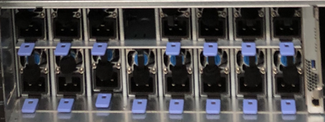
Power Supply
To remove a CN5000 Switch power supply:
Press the thumb tab inward and grasp the handle to gently slide the module out of the slot.
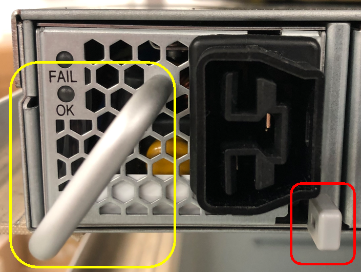
Note
Handle is highlighted yellow; thumb tab is highlighted red.
To insert a CN5000 Switch power supply:
Grasp the module by the handle and gently slide it into an open slot until the unit engages with the connector.
When fully inserted, the module sits flush with the chassis and the thumb tab is locked.
Fans
To remove a CN5000 Switch fan:
Press the thumb tab inward and grasp the handle to gently slide the module out of the slot.
Note
Handle is highlighted yellow; thumb tab is highlighted red.
To insert a CN5000 Switch fan:
Grasp the module by the handle and gently slide it into an open slot until the module engages with the connector.
When fully inserted, the module sits flush with the switch and the thumb tab is locked.
7.3.1.1.2. Replacing the DCS Modules
Leaf Modules
To remove a DCS Leaf module:
Grasp and pull the release arms (top and bottom) out and away from the module body.
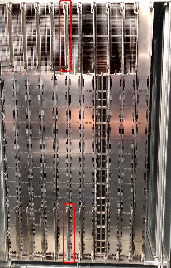
Note
Release arms are highlighted red.
Gently pull the module out of the chassis.
Caution
Never pull on the release arms when removing the modules from the slots.
To insert a DCS Leaf module into a chassis:
Grasp and pull the release arms (top and bottom) out and away from the module body.
Gently slide the module straight into an applicable open slot until it engages with the DCS chassis.
Caution
Never push on the release arms when sliding the modules into the applicable slots. Always apply pressure to the middle of the module.
Push the release arms in until they lock in place.
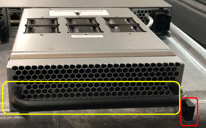
Fan Tray Modules
Note
Air baffles are located on the back side of the fan tray modules.
To remove a DCS Fan Tray module:
Grasp and squeeze the handles inward to release the module.
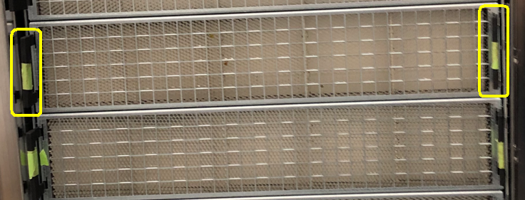
Note
Handles are highlighted yellow.
Gently slide the module out of the slot.
To insert a DCS Fan Tray module:
Gently slide the module into an open slot until the unit engages with the chassis.
When fully inserted, the module locks into place and sits flush with the chassis.
Spine Modules
To remove the Spine module:
Remove the fan tray module as described in Fan Tray Modules.
Behind each fan tray are two Spine modules.
Press the thumb tabs inward to release the lock.
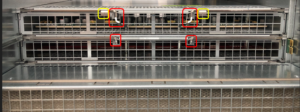
Note
Handles are highlighted yellow; thumb tabs are highlighted red.
Grasp the handles (if the top module) or the module itself (if without handles) to gently slide the module out of the slot.
To insert a Spine module:
Ensure the thumb tabs are pressed inward to retract the locking mechanism.
Gently slide the module straight into an applicable open slot until it engages with the DCS chassis.
Press the thumb tabs outward to engage the lock.
Reinsert the fan tray module as described in Fan Tray Modules.
Management Modules
To remove a DCS Management module:
Grasp the bottom handle and lift upward to release the module
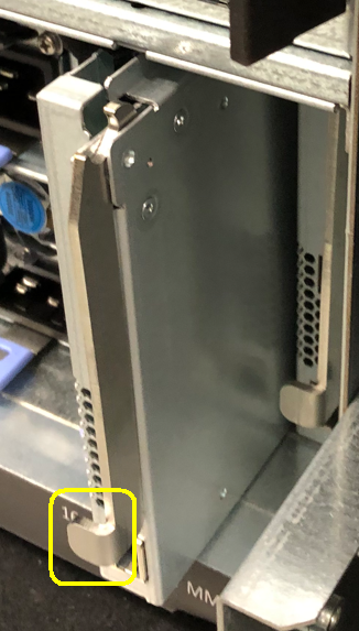
Note
Handle is highlighted yellow.
Gently pull the module out of the slot.
To insert a DCS Management module:
Gently slide the module straight into the open slot until it engages with the chassis.
When fully inserted, the module is locked.
Power Supplies Modules
To remove a DCS Power Supply module:
Position the handle at the center of the fan, if previously moved off to the side.
Lift the release tab, then grasp the module by the handle and gently slide it out of the slot.
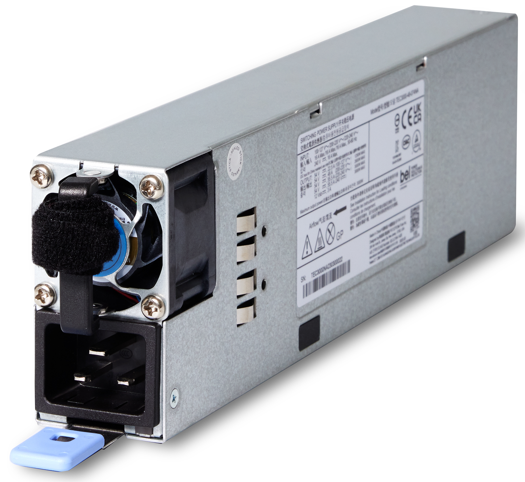
To install a DCS Power Supply module:
Grasp the module by the handle and gently slide it into an open slot until the unit engages with the connector.
When fully inserted, the module sits flush with the chassis and the thumb tab is locked.