3.3.3. Director Class Switch Installation
This section describes the rack mounting instructions for the CN5000 Omni-Path Director Class Switch (DCS) in a four-post, standard-depth rack. A 30-inch wide rack is recommended. If two DCS switches are installed in one rack, Cornelis recommends using a 45U x 30-inch wide rack.
In a standard-depth rack, the distance between the front and back mounting posts is approximately 28 inches (700 mm). Mounting rails for the DCS are adjustable to accommodate racks with 26–32 inches between mounting posts.
3.3.3.1. Unpacking the DCS
The DCS should arrive in good condition. Before unpacking, check for any obvious damage to the packaging. If any damage to the packaging or the contents is found, notify the reseller immediately.
Note
Set aside packaging materials in case the switch requires return shipment.
The following steps provide a high-level overview for unpacking a DCS.
Remove strapping, lid, and sleeve.
Remove strapping from interior boxes. The boxes strapped to the side of the DCS are the Accessory box, Installation kit, and Wire Management box. If the DCS is liquid cooled, a Manifold-to-Module tube assembly box is also included.
Remove the plastic bag.
Remove the screws from the brackets securing the DCS to the pallet.
Slide the DCS off of the pallet.
3.3.3.1.1. Verify DCS Package Contents
Ensure the Director Class Switch package contents match the packing list.
3.3.3.1.2. Visually Inspect the DCS
Check the switch for visual damage and then return the switch to its container until it is ready to install. If damage is noted or suspected, do not install the switch. Contact Cornelis Technical Support or your reseller for assistance.
Never attempt to install or use a damaged DCS.
3.3.3.1.3. Verify the Mounting Kit Package Contents
Ensure the Mounting Kit package contents match the packing list.
3.3.3.1.4. Tools Required
Tools required for this installation include the following:
An ESD wrist strap or other personal grounding device
A #0 and #2 Phillips screwdriver
An M6 HEX nut wrench
Torque wrench
Open sockets or open wrenches
3.3.3.2. Installing the DCS
This section outlines the steps necessary to install a Director Class Switch (DCS).
3.3.3.2.1. Mark the Rack
Determine the location in the rack for the bottom of the switch.
Mark the upper (if applicable) and lower mounting positions on the vertical rails on the front of the rack.
Mark the upper (if applicable) and lower mounting positions on the vertical rails on the back of the rack.
3.3.3.2.2. Install the Mounting Kit and DCS
The DCS mounting kit has two (left and right) adjustable shelves and two (left and right) long vertical brackets that attach the DCS chassis to the rack frame.
Note
Cornelis recommends using cabinet anti-tip devices. This is especially true if installing or removing a switch in the upper half of the cabinet when the lower half is empty.
Note
A 30" wide rack is recommended for all DCS installations. A 45U x 30" rack is recommended if installing two DCS switches. Installation in a 24" rack will be supported if limited to a single DCS.
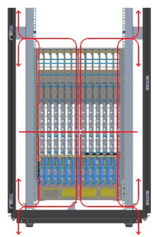
Adjust the interior vertical rack rails as shown below.
Figure 41. Adjust Rack Vertical Rails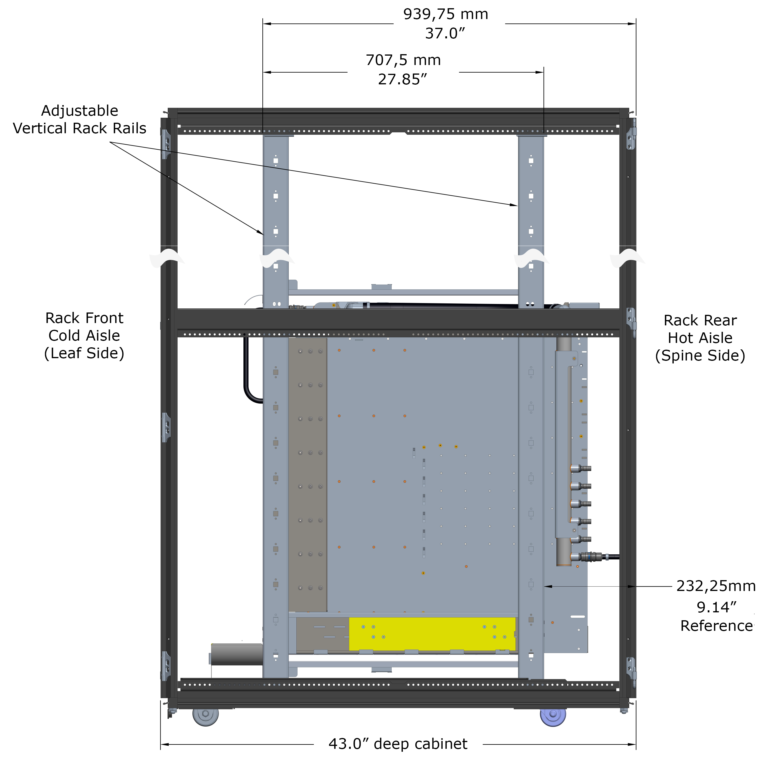
Install the two disposable fixture brackets to the frame at the desired U height; one to the front posts, one to the rear posts.
Figure 42. Install Disposable Fixture Brackets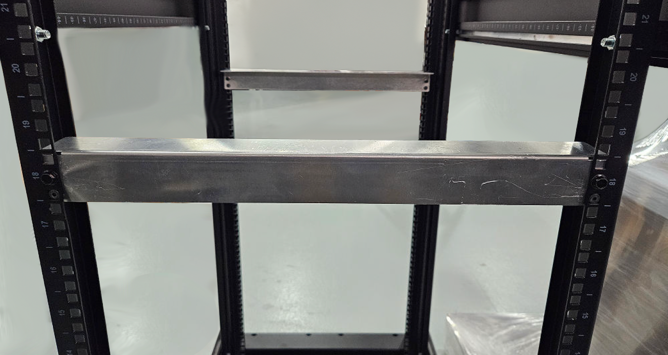
Remove the four screws from the adjustable shelves and set them aside for later installation. Leave the shelves loose.
Figure 43. Set Adjustable Shelves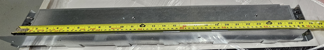
Install the two shelves on top of the fixture brackets. Ensure the fixed section of each shelf is affixed to the Leaf side of where the DCS will sit. Washers may be required for racks with larger screw holes.
Figure 44. Install Adjustable Shelves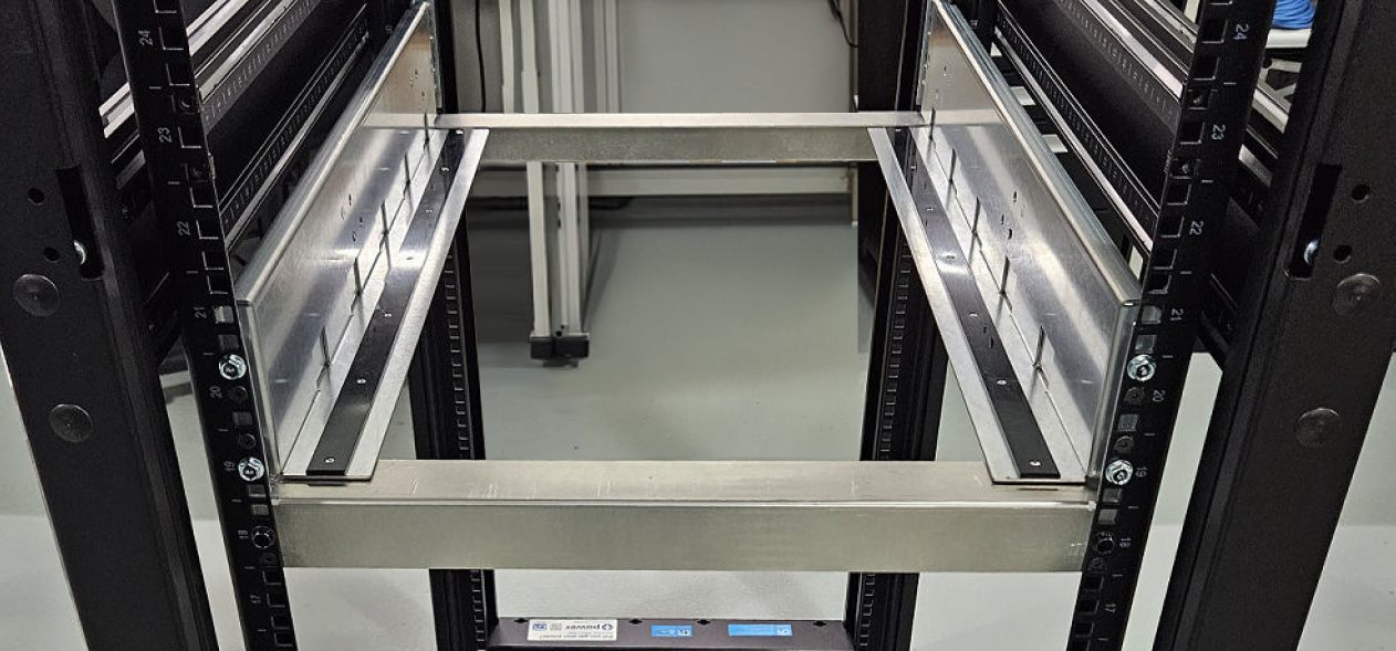 Figure 45. Shelf Alignment
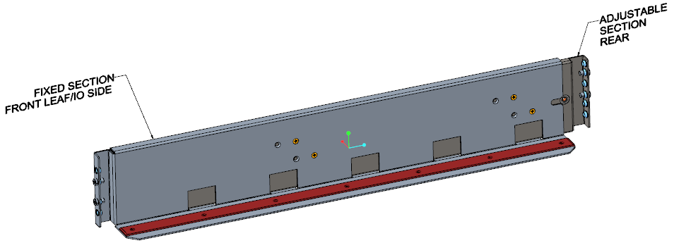
Insert and tighten the screws on the adjustable shelves (removed in step 2).
Figure 46. Adjustable Shelves Installed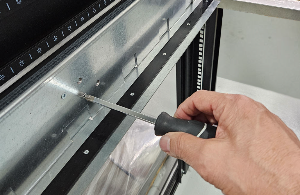
Remove and discard, or recycle, the fixture brackets.
Figure 47. Fixture Brackets Removed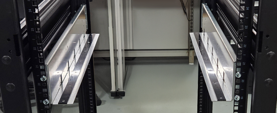
Install the two vertical brackets to the frame but leave them loose for attaching them to the DCS chassis.
Note
Ensure that the vertical brackets are attached to the Cold Aisle side of the cabinet and that the Leaf side of the DCS is being attached to the vertical brackets.
Figure 48. Loosely Install Vertical Brackets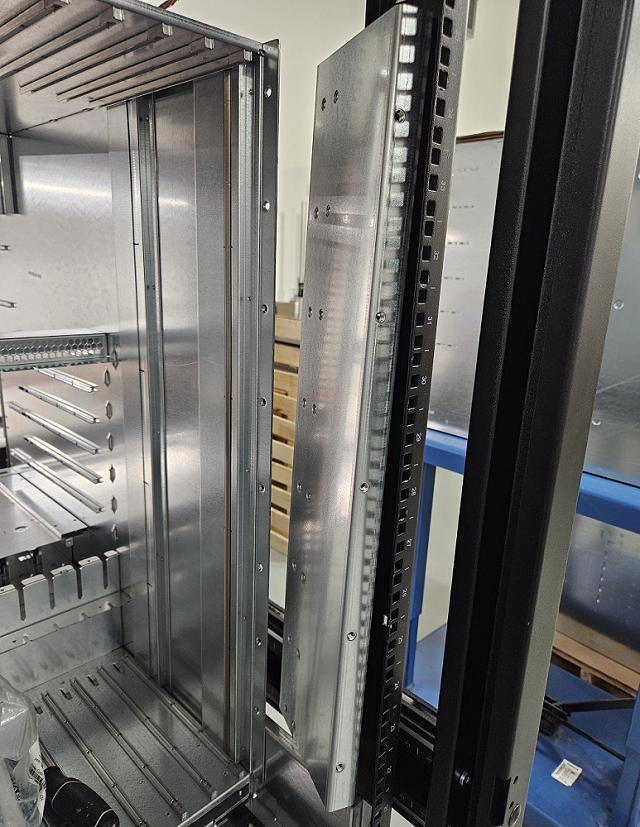
Modules removed from DCS chassis to help improve clarity.
Figure 49. Vertical Bracket Orientation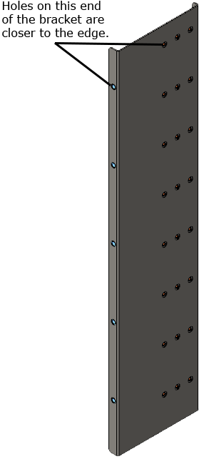
Using a server lift, slide the DCS onto the shelves so that the attachment holes in the DCS approximately align with those in the two vertical brackets installed in step 7.
If installing a liquid-cooled DCS, perform the following:
Temporarily remove the single fan module from the DCS.
Figure 50. Remove Fan Module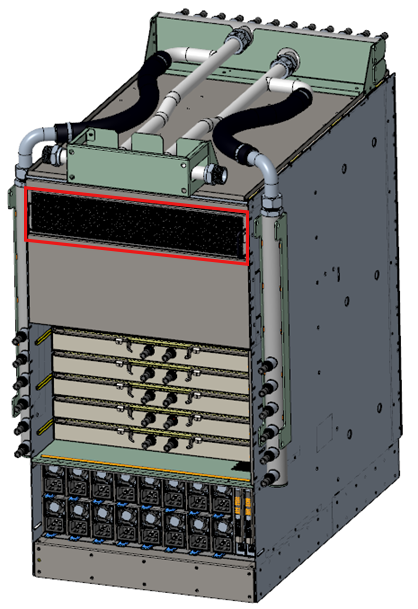
Remove the four screws holding the two side manifolds to the DCS and set them aside for later.
Figure 51. Remove Four Manifold Screws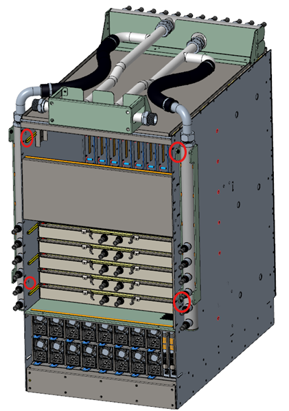
Set the manifolds to rest behind the DCS. This will allow the DCS to be installed into the rack.
Secure the DCS to the vertical brackets with screws. Tighten the screws to the front frame post.
Figure 52. DCS with Mounting Kit Installed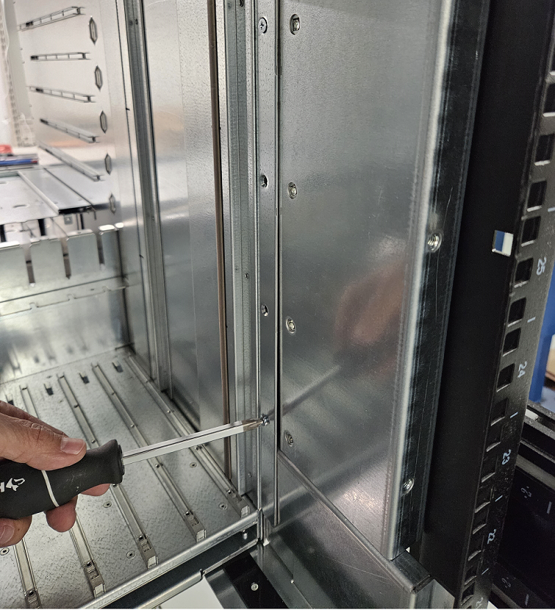
DCS modules removed to help improve clarity.
Secure the fan-side of the DCS to the cabinet using the shipping brackets (A00322 and A00324) and screws.
Figure 53. Install Shipping Brackets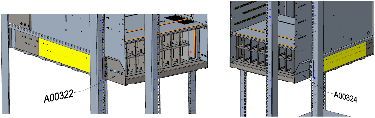
If installing an air-cooled DCS, skip to Connect the Power Cables. If installing a liquid-cooled DCS:
Use the screws from step 9 to secure the side manifolds.
Reinstall the fan module.
3.3.3.2.3. Completing Liquid-Cooled Installations
A liquid-cooled DCS is purged of liquid before shipping and then filled with nitrogen. This allows the customer to choose which working fluid to use (deionized water with additives, Propylene Glycol, or Ethylene Glycol). The quick disconnects (QDs) are Staubli SCG06 and are color-coded to indicate flow direction.
Follow the instructions for installing the air-cooled DCS.
Install all modules if not already installed.
On the port side, connect the color-coded tubing (red/outlet and blue/inlet) from the manifold to each Leaf.
Figure 54. DCS Port Side Tubing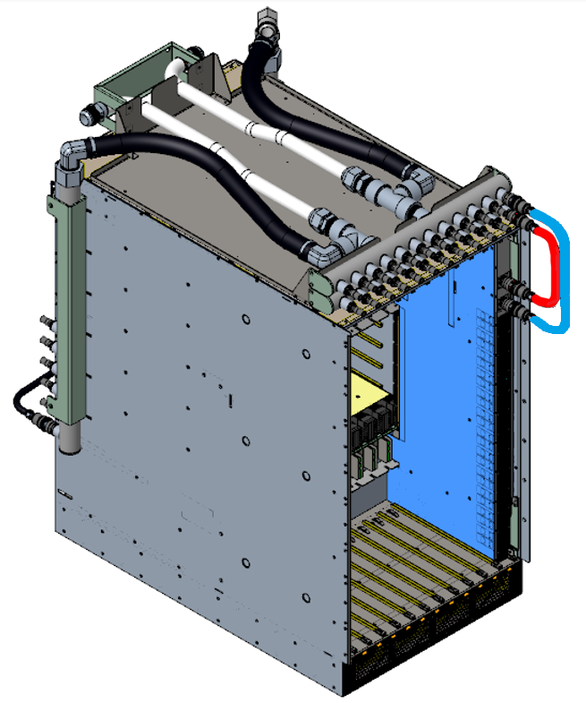
On the spine side, connect the color-coded tubing (red/outlet and blue/inlet) from the manifold to each Spine.
Figure 55. DCS Spine Side Tubing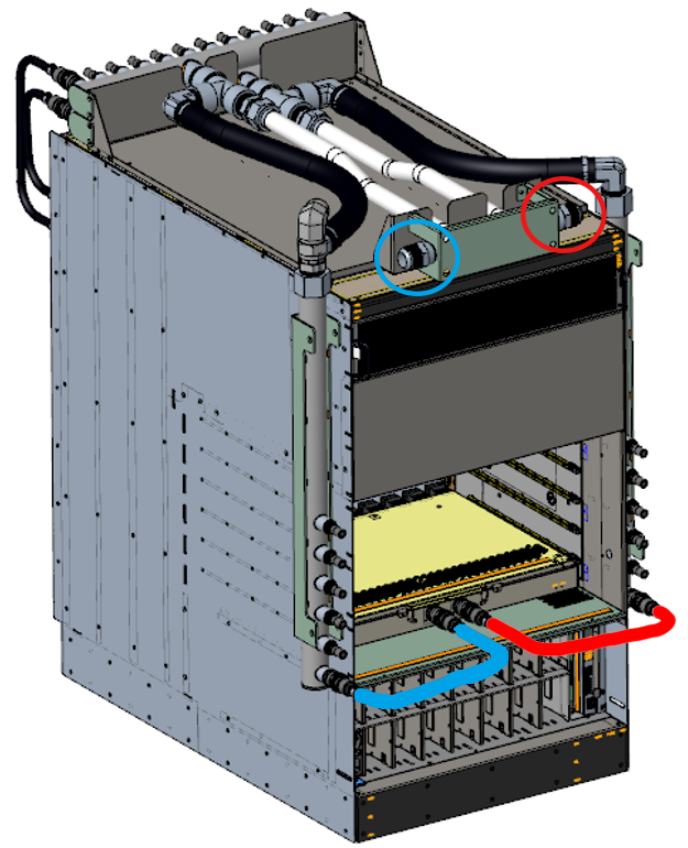
Purge the DCS of nitrogen.
Connect the cooling infrastructure to the DCS via the connections on the top, fan-side of the DCS as shown in Figure 55, “DCS Spine Side Tubing”.
Note
Integrators will need to supply their own connections from the Switch to the cooling infrastructure.
Fill the DCS with the desired working liquid (deionized water with additives, Propylene Glycol, or Ethylene Glycol).
3.3.3.2.4. Connect the Power Cables
Note
For each power supply installed, a power cord must be installed in its corresponding power inlet.
Connect the power cables to a power distribution unit (PDU) or an AC power outlet.
Press the power on button on the CEB module.
The system powers up.
The fans start.
The system performs a power-on self-test.
The switch power supplies and fan LEDs light up.
3.3.3.3. Cabling the DCS
Note
Install the cable management trays prior to routing any cables to the DCS.
Leaf cables should be run directly up or down from their ports due to the Leaf's vertical orientation and to maintain the ability to hot-swap them. The cables will route Up/Down to the cable management hardware, then left/right to sides of the rack, then up/down to overhead/under the floor cable entry locations.
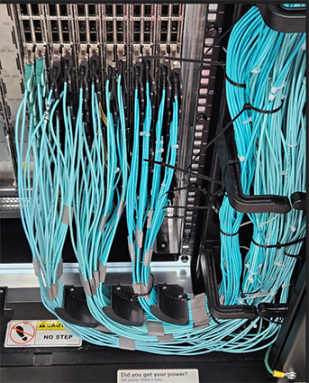
Using the ports on the leaf, connect the switch to the host(s) or switch(es) using QSFP cables. Note that the top 24 ports of each leaf should be routed up, while the bottom 24 ports of each leaf should be routed down.
Refer to your cable planning spreadsheet as described in Fabric Design Prerequisites.
3.3.3.3.1. Procedure
Caution
It is important to provide strain relief for the QSFP cable connector.
Use two M6 screws to secure one of the Cable Management Trays to the cabinet at the bottom of the DCS. Ensure the tray is oriented correctly for the bottom tray and positioned as shown below.
Figure 57. Bottom Cable Management Tray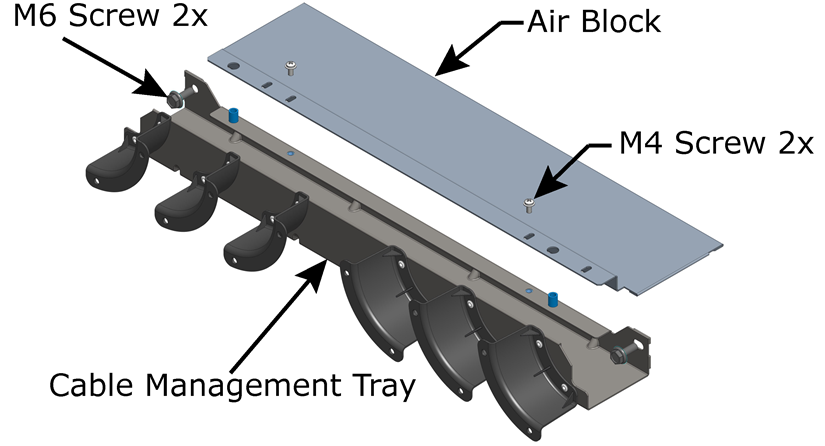 Figure 58. Bottom Tray Positioning
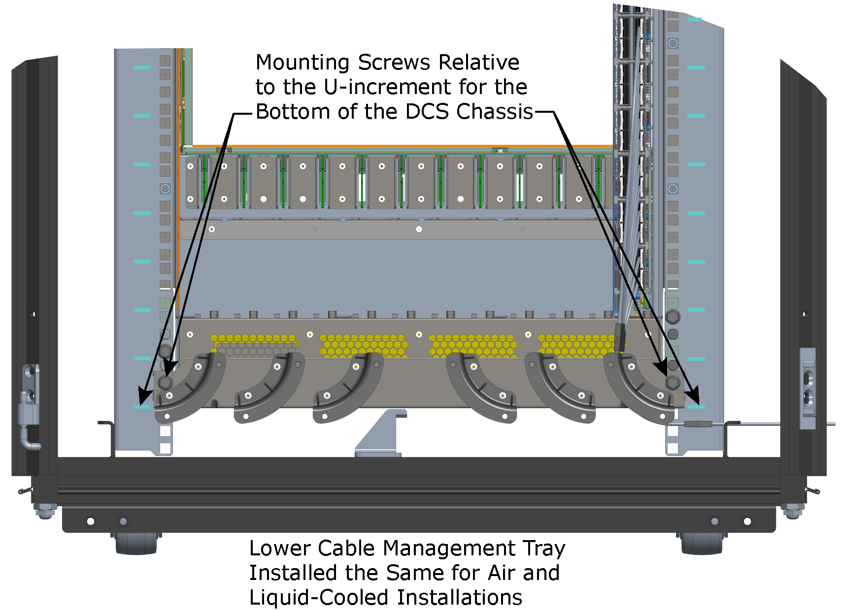
Slide one of the Air Blocks into the space between the bottom of the DCS and the top of the bottom Cable Management Tray. Ensure the Air Block aligns with the pins on top of the tray.
Use two M4 screws to secure the Air Block to the top of the bottom Cable Management Tray.
Use two M6 screws and two M6 cage nuts to secure the second Cable Management Tray to the cabinet at the top of the DCS. Ensure the tray is oriented correctly for the top tray and positioned (for air- or liquid-cooled installation) as shown in Figure 60, “Air-Cooled Installations” and Figure 61, “Liquid-Cooled Installations”.
Figure 59. Top Cable Management Tray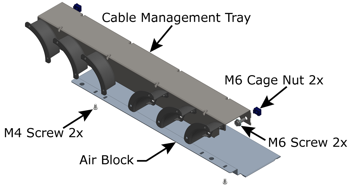 Figure 60. Air-Cooled Installations
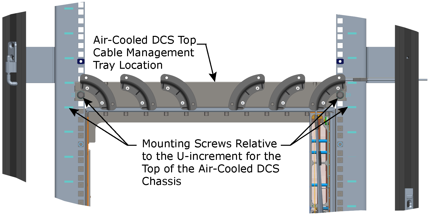 Figure 61. Liquid-Cooled Installations
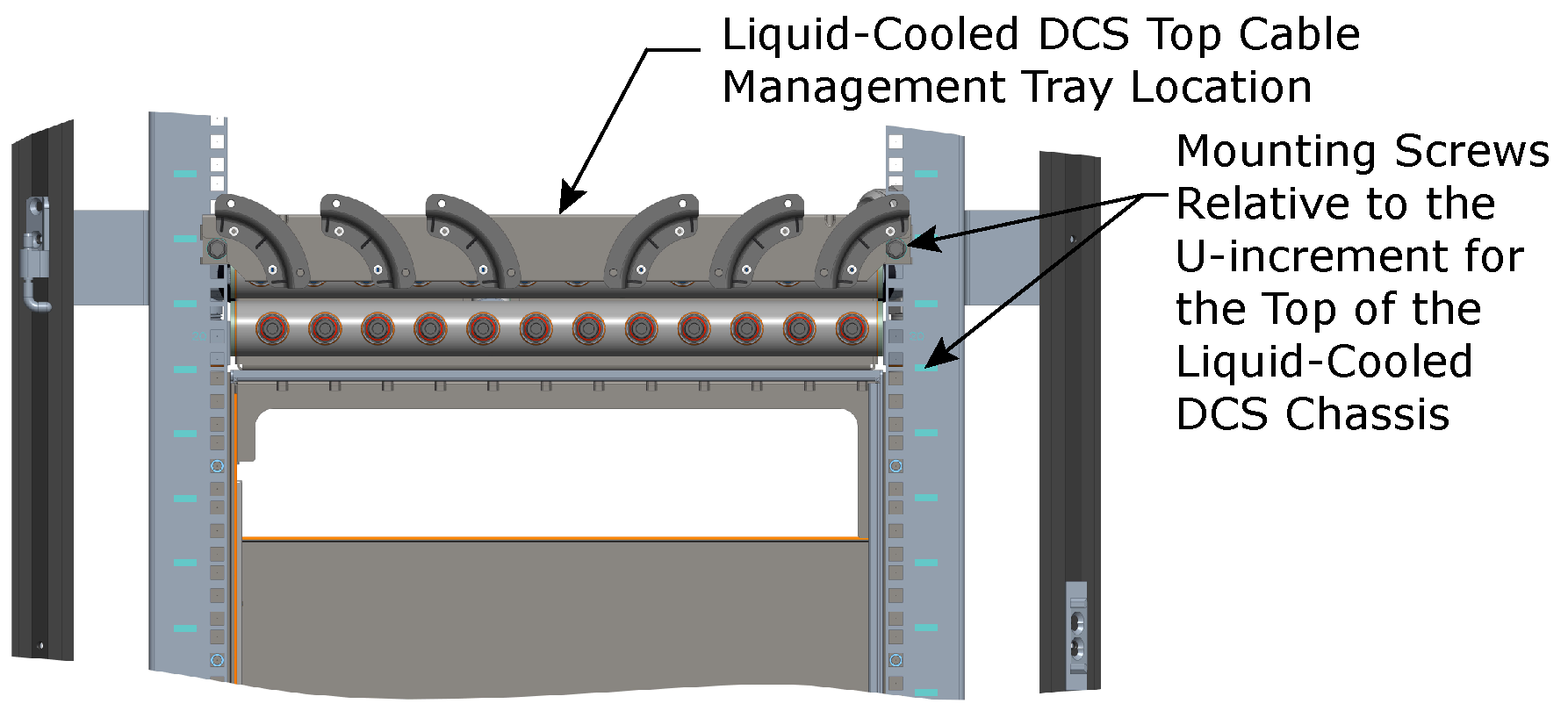
Slide the other Air Block into the space between the top of the DCS and the bottom of the Cable Management Tray. Ensure the Air Block aligns with the pins on the bottom of the tray.
Use two M4 screws to secure the Air Block to the bottom of the top Cable Management Tray.
When cabling, use the 1x6 and 1x12 Cable Ties as shown below to help secure, guide, and support the cables.
Figure 62. Cable Ties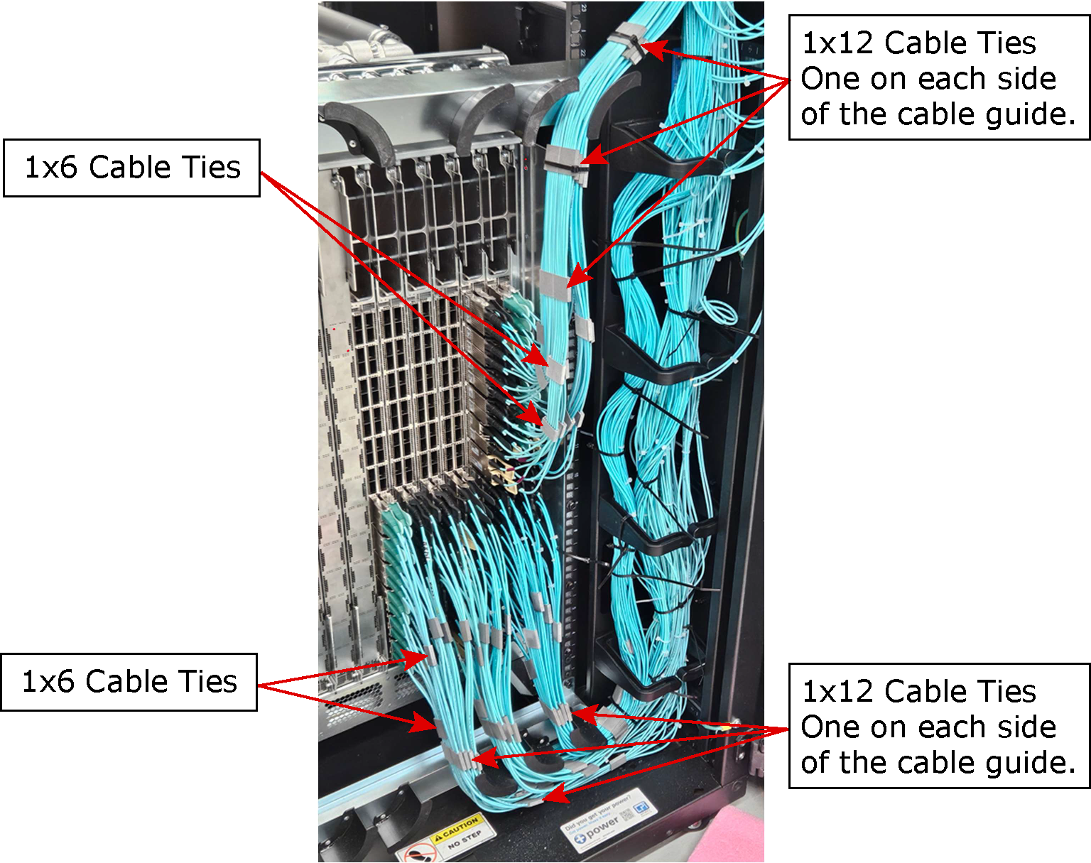
3.3.3.3.2. DCS Slot and Port Numbering
The following figures detail the module slot numbering and the leaf slot numbering schema for the DCS.