4.3.3. 2-Tier Fat Trees
The 1-tier tree topology, while simple, is limited by the number of ports available on a single switch. To overcome this limitation while maintaining reasonable bandwidth between endpoints, a 2-tier fat tree topology can be employed. This topology is often referred to as a spine-leaf architecture in data center environments.
In a 2-tier fat tree, the network is organized into two distinct layers: a leaf layer and a spine layer. The leaf switches connect directly to endpoints such as compute nodes, while the spine switches serve as the backbone of the network, connecting only to leaf switches. Each leaf switch connects to every spine switch, allowing for communication between the two layers.
Note
Notice that the terminology here mirrors that of the spine and leaf module designations used by the DCS. This is intentional, as the internal topology of a DCS is that of a 2-tier fat tree.
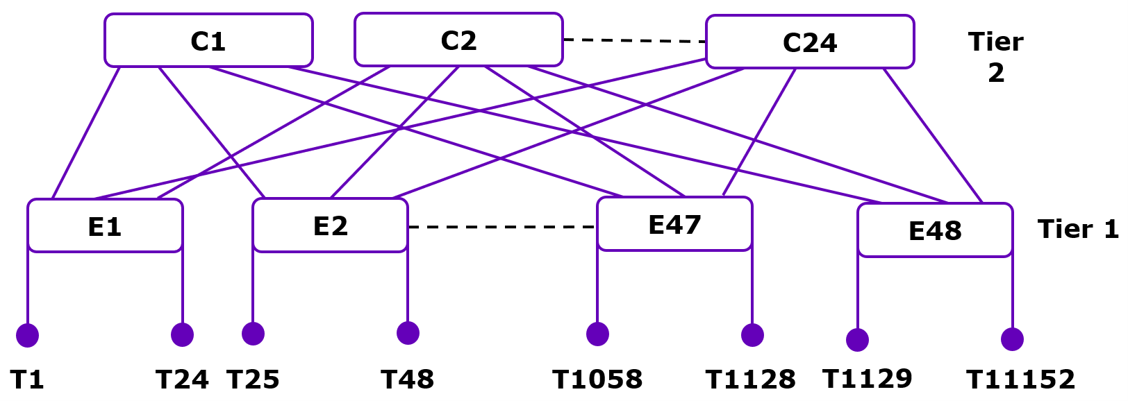
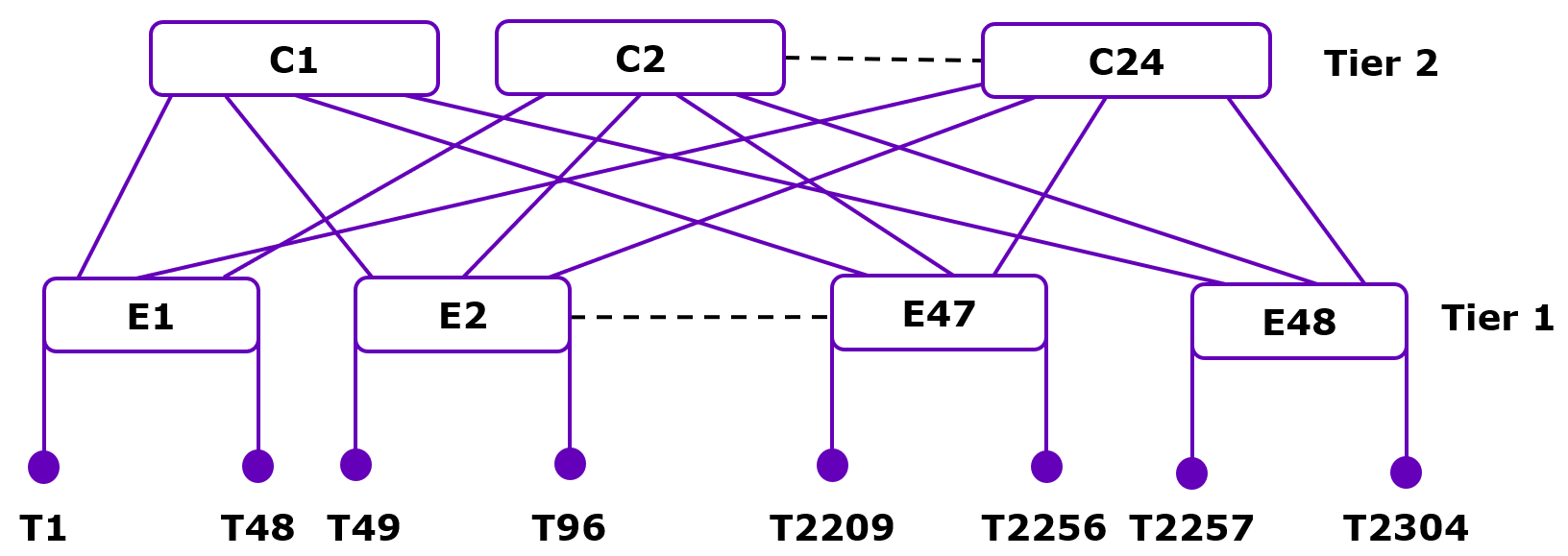
Consider a 2-tier fat tree constructed with CN5000 Switches in a non-blocking configuration. In this configuration, each leaf switch can connect to 24 endpoints with 400 Gbps native connections (see Figure 67) or 48 200 Gbps subdivided connections (see Figure 68), while also maintaining uplinks to each spine switch. The spine switches, also CN5000 Switches, serve solely to interconnect the leaf switches. The resultant fabrics can be much larger than a single switch, allowing up to 1152 endpoints in the native configuration and up to 2304 endpoints in the subdivided configuration.
4.3.3.1. Advantages
The key advantage of this topology lies in its ability to provide predictable, low-latency communication between any two endpoints in the network. Provided that two endpoints are not connected to the same leaf switch, the communication path between them will always traverse exactly three hops:
From the source endpoint to its leaf switch.
From the leaf switch to a spine switch.
From the spine switch to the destination leaf switch and endpoint.
Unlike the 1-tier tree, where bandwidth between switches becomes a bottleneck, the 2-tier fat tree addresses this issue through multiple parallel paths. When two endpoints connected to different leaf switches need to communicate, the traffic can be distributed across multiple spine switches. This distribution of traffic is a fundamental characteristic of fat tree topologies and is the origin of the term fat—the aggregate bandwidth between any two leaf switches grows fatter with the addition of more spine switches.
To illustrate this concept, consider a 2-tier fat tree with four leaf switches and four spine switches, where each switch is a CN5000 Switch. Each leaf switch connects to the spine switches through four ISLs, one to each spine switch. If we were to bisect this network by cutting through the connections between the leaf and spine layers, we would have sixteen ISLs in total. This results in a bisection bandwidth that is sixteen times that of a single ISL, dramatically reducing the bottleneck effect seen in the 1-tier configuration.
The number of parallel paths available between any two leaf switches is equal to the number of spine switches. This means that as the number of spine switches increases, so does the bisection bandwidth of the network. This scalability is a significant advantage of the 2-tier fat tree topology.
Another benefit of the 2-tier fat tree is its modularity. Additional leaf switches can be added to accommodate more endpoints without changing the existing structure, provided there are sufficient ports available on the spine switches. Similarly, additional spine switches can be added to increase the bisection bandwidth of the network.
The 2-tier fat tree also offers improved fault tolerance compared to a 1-tier tree. In a 1-tier tree, the failure of an ISL between two switches can isolate portions of the network. In a 2-tier fat tree, the failure of a single ISL or even an entire spine switch does not isolate any portion of the network, as alternative paths remain available through other spine switches.
4.3.3.2. Limitations
It is worth noting that the 2-tier fat tree topology is not without its limitations. The number of endpoints that can be supported is constrained by the number of ports available on the leaf switches for endpoint connections, as well as the number of leaf switches that can be connected to the spine layer. Additionally, as the network scales, the number of ISLs required grows quadratically with the number of leaf and spine switches, which can lead to increased complexity and cost.
Despite these limitations, the 2-tier fat tree topology represents a significant improvement over the 1-tier tree in terms of bandwidth, scalability, and fault tolerance, making it a popular choice for medium-sized network deployments where these characteristics are valued.