2.3.2. CN5000 Switch
Building on the Omni-Path Fabric Architecture, the CN5000 Switch provides 48 low-latency, 400 Gbps ports, 32 of which can be subdivided into two 200 Gbps links through cabling allowing for a maximum of 80 connections.
The CN5000 Switch provides two out-of-band user access interfaces: an RJ45 10/100/1000 Ethernet BASE-T port and a USB Type A serial port. These are located on the rear panel of the CN5000 Switch. The Ethernet port provides access to the Baseboard Management Controller (BMC) while the USB port provides serial access to the BMC. DHCP is enabled by default for Ethernet communication. The USB is for serial IO and does not offer any power capabilities.
The CN5000 Switch is offered in air-cooled and liquid-cooled configurations. The switch supports two airflow patterns, Fan-to-Port or Port-to-Fan. Color-coded latch pull-tabs on the power supplies correspond to fan tray configurations for easy identification. Power is supplied by a hot-swappable, AC or DC, power supply with the following specifications:
AC Power Configuration: 200-277 VAC, 50-60 Hz input
DC Power Configuration: 48 VDC input (hot pluggable)
Note
The CN5000 Switch is interoperable with the Cornelis Omni-Path Express 100 Series (OPA100) Edge Switch, Director Class Switch, and Host Fabric Interface adapter. In these cases, the links will operate at 100 Gbps total bandwidth (25 Gbps per lane).
When connecting OPA100 devices to a CN5000 fabric, the Fabric Manager must be located on a CN5000 host.
2.3.2.1. Switch Feature Summary
The CN5000 Switch delivers enterprise-class performance and flexibility with advanced routing capabilities, comprehensive management features, and industry-leading bandwidth for modern data center requirements. Key features include the following:
48 high-performance ports, each capable of delivering 400 Gbps throughput
32 ports with flexible subdivision support, allowing independent configuration as 2 x 200 Gbps channels
38.4 Tbps aggregate bandwidth capacity for demanding workloads
Optimized architecture for superior message rates
QSFP112 interface for versatile connectivity options
2.3.2.1.1. Management
In-band and out-of-band management options: Offers flexible connectivity allowing administrators to choose their preferred management approach based on network architecture and security requirements
Command line interface through 10/100/1000 BASE-T Ethernet: Enables direct network-based interaction for configuration and monitoring tasks
Serial console through USB A serial port: Provides local management access for troubleshooting and initial configuration scenarios
Network Time Protocol (NTP) and LDAP support: Ensures accurate time synchronization across the fabric and enables centralized authentication and user management for seamless integration into existing enterprise infrastructures
2.3.2.2. Switch Physical Specifications
This section provides a high-level overview of the Switch physical specifications.
Mounting
19-inch rack (Rails have adjustable depth mounting from 26 to 32 in.)
Chassis can be mounted flush with the rack EIA flanges or recessed and locked in place
Mountable: High-speed fabric ports facing the front or back of the rack
Dimensions
1.7 x 17.2 x 26.1 in. (4.40 x 43.79 x 66.30 cm) (H x W x D)
Weight
Liquid-cooled:
AC Power: TBD lb (TBD kg)
DC Power: TBD lb (TBD kg)
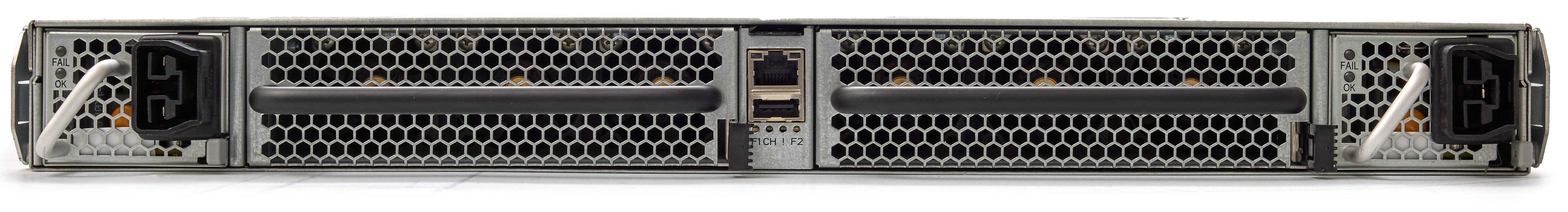
2.3.2.3. Switch LEDs
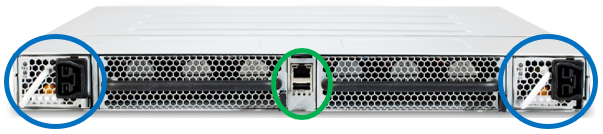
The chassis status LEDs (Ethernet and USB) are located in the center of the switch (green oval) shown in the following figure. Each power supply, located at the left and right sides of the switch (blue ovals), has LED indicators.
2.3.2.3.1. Chassis Status LEDs
The following figure shows the chassis status indicators for Ethernet (top) and USB (bottom).
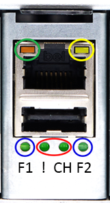
The following list describes the LEDs shown in the preceding figure.
Two Ethernet indicators
Left, Orange (green oval)
Off = No Link
On = Link
Right, Yellow (yellow oval)
Solid On = No Activity
Blinking = Activity
Two Fan Tray status indicators on the chassis (blue circles), bicolored, one per tray
Green = On and operating normally
Amber = Requires attention
Two Chassis indicators (red oval)
Green = On and operating normally
Blinking Amber = Requires attention
Both Off = No Power
2.3.2.3.2. Power Supply Status LEDs
There are two LEDs per power supply, OK (Blue) and Fail (Amber). They are circled in the following figure.
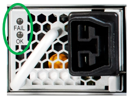
AC Power Supply
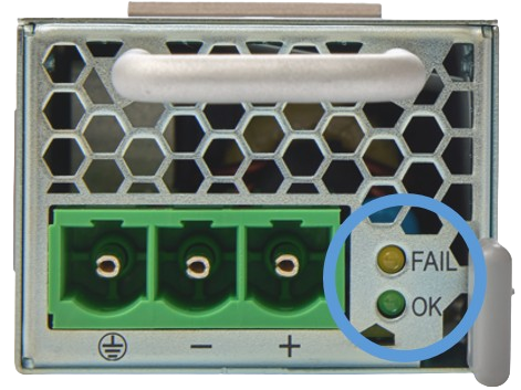
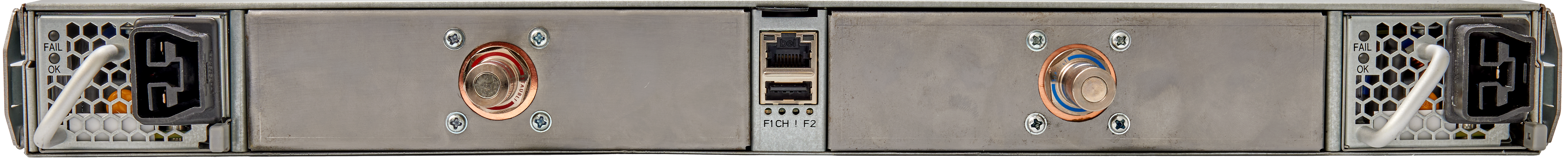
DC Power Supply
The LEDs are used together. Their combined meanings are described in the following table.
Power Supply State | OK | FAIL |
|---|---|---|
Active | On | Off |
Standby | 1 Hz Blink | Off |
No AC/DC Input Power | Off | Off |
Warning or no AC/DC Input Power to PSU | Off | 1 Hz Blink |
Fault | Off | On |
2.3.2.4. Switch Cooling Configurations
The CN5000 Switch is available in both air-cooled and liquid-cooled configurations to accommodate different data center thermal management infrastructures and efficiency requirements.
2.3.2.4.1. Air-Cooled Variant
The air-cooled variant uses traditional forced-air cooling through a redundant cooling system comprised of two hot-pluggable fan tray assemblies. Each tray contains six fans arranged in three tandem pairs for optimized airflow efficiency. The system supports both Fan-to-Port (forward) and Port-to-Fan (reverse) airflow configurations to accommodate different data center cooling architectures. Note that the airflow direction must be factory-configured and cannot be changed in the field.
To ensure proper installation and prevent airflow configuration mismatches, each fan tray features a color-coded pull-tab on the latch mechanism. The configured airflow direction is automatically reported to the switch management system and Omni-Path fabric management tools for operational visibility. It should be noted that the DC-powered variant of the CN5000 Switch supports only Port-to-Fan airflow configuration due to thermal design constraints specific to that power architecture.
2.3.2.4.2. Liquid-Cooled Variant
The liquid-cooled variant of the CN5000 Switch employs a comprehensive direct and indirect liquid cooling architecture to achieve superior thermal management efficiency. The system's primary cooling targets include the switch ASIC, QSFP optical modules, and voltage regulators, with the liquid cooling subsystem supporting inlet temperatures up to 45 °C at the chassis interface. This advanced cooling solution achieves exceptional thermal performance with up to 94% of the system's heat capture transferred to the liquid cooling loop, depending on the specific cable configuration deployed. The hydraulic interface uses industry-standard Staubli SCG06 quick disconnect couplings featuring integrated color indicators that provide visual confirmation of proper flow direction and connection status, ensuring safe and reliable maintenance operations.
For leak detection and prevention, the system employs an indirect monitoring approach that relies on the rack-level Coolant Distribution Unit (CDU) infrastructure to continuously monitor critical flow parameters including flow rate, pressure differentials, and temperature gradients. This enables early detection of potential leak risks and alerts operators before critical failures occur. The liquid-wetted components that come into direct contact with the cooling liquid are limited to the quick disconnect couplings, internal tubing pathways, and the precision-engineered cooling plate assemblies that interface directly with the ASIC, QSFP modules, and voltage regulators. This minimizes potential failure points while maximizing thermal transfer efficiency through optimized material selection and flow path design.
The cooling system supports multiple coolant types to accommodate different data center liquid cooling infrastructures, including:
Deionized water with appropriate corrosion inhibitors and biocides
Propylene glycol-based solutions for freeze protection in cold climates
Ethylene glycol mixtures where higher thermal performance is required
2.3.2.5. High-Speed Fabric Ports
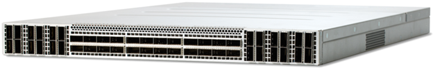
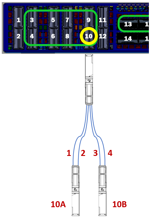
The high-speed QSFP112 fabric ports of the CN5000 Switch are located on the front panel of the switch as shown in the following figure. In addition, ports capable of port subdivision are bounded by the green boxes in the figure.
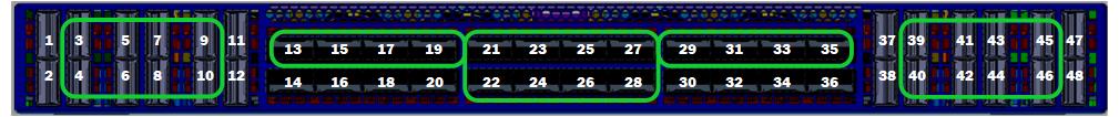
Port subdivision, supported on 32 of the 48 QSFP ports, splits a single QSFP port’s 4 x 100 Gbps lanes into two independent, 2 x 100 Gbps lanes per QSFP port. This yields a total of 80 port connections consisting of 64 200 Gbps port connections and 16 400 Gbps port connections. The remaining 16 ports do not support subdivision but can be operated at a reduced bandwidth of 200 Gbps. Numbering for the subdivided 2-lane ports uses the following convention:
QSFP port number concatenated with “A” or “B”, where “A” is the port comprised of lanes 1 and 2, and “B” is the port comprised of lanes 3 and 4.
For example, Port 10 highlighted in Figure 12 shows how the lanes are split between the two QSFP ports as Fabric ports 10A and 10B. Split cables that support this sub-divided lane scheme map lane three and four from the switch to lane one and two in the “B” module of the cable.
Omni-Path 100 endpoints may be connected to the CN5000 Switch. When an Omni-Path endpoint is connected to a CN5000 Switch port, that port will operate with Omni-Path 100 capabilities.
Note
Omni-Path 100 is not interoperable with subdivided ports and split cables.