4.3.5. 3-Tier Fat Trees
While 2-tier fat trees are simple and effective, they are limited in size. For larger-scale deployments, a 3-tier fat tree topology provides the necessary scalability while maintaining the bandwidth and fault tolerance advantages of fat tree architectures.
A 3-tier fat tree introduces an additional layer of switches between the leaf and spine tiers. This middle tier, often referred to as the aggregation tier, creates a hierarchical structure that allows for significantly more endpoints to be connected to the fabric. In the context of CN5000 deployments, this topology can be implemented using all CN5000 Switches or a combination of CN5000 Switches and Director Class Switches.
In a 3-tier fat tree constructed entirely with CN5000 Switches, the network is organized into distinct pods. Each pod consists of a set of CN5000 Switches that connect directly to endpoints, and a set of aggregation switches that connect the edge (leaf) switches to the core (spine) tier. The core tier switches then interconnect the various pods, enabling communication between endpoints in different pods.
Consider a full 3-tier fat tree with 1:1 subscription using only CN5000 Switches as shown in the following figure. This configuration can support up to 27,648 endpoints, a scale far beyond what is achievable with a 2-tier topology. The fabric consists of 48 compute pods, highlighted in gray, each containing 24 edge switches and 24 aggregation switches. Each edge switch connects to 24 endpoints, resulting in 576 endpoints per pod. The 48 pods are then interconnected via 576 core switches in the third tier.
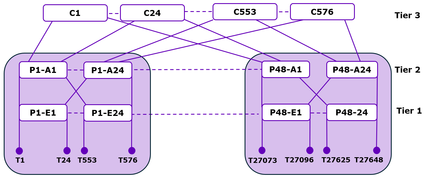
The core switches in a 3-tier fat tree can be logically grouped based on their connectivity patterns. Sets of 24 core switches that connect to the same set of 24 aggregation switches form what is known as a Core Group. These Core Groups, along with the aggregation switches they connect to, can be considered Core Pods, although the aggregation switches retain the pod ID of the compute pod they belong to.
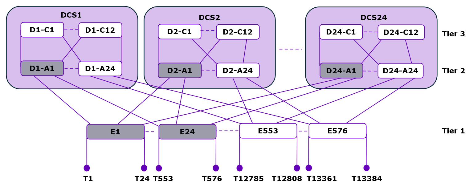
An alternative implementation of a 3-tier fat tree can use DCSes for the aggregation and core tiers as shown in the following figure. A DCS can be configured with anywhere from 48 to 576 ports in increments of 48, providing flexibility in the design of the fabric. When using a DCS for the upper tiers, the maximum scale of the system is limited to 13,824 endpoints with native links. However, if the endpoints on the edge switches are configured with subdivided links, this number can be doubled to 27,648 endpoints, although at half the bandwidth per endpoint.
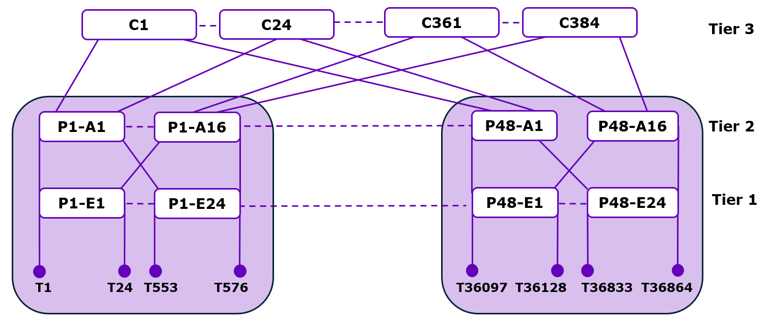
Oversubscription can also be applied to 3-tier fat trees as shown in the following figure. A 3-tier fat tree with 2:1 oversubscription at the edge tier allows for more endpoints to be connected to each edge switch, at the cost of potential bandwidth bottlenecks between the edge and aggregation tiers. This approach can be implemented with all CN5000 Switches or a combination of CN5000 Switches and DCSs.
The decision between using a 2-tier or 3-tier fat tree topology depends on several factors, including the number of endpoints to be connected, the bandwidth requirements, and the available equipment. For smaller deployments, a 2-tier topology may be sufficient and more cost-effective. For larger deployments, particularly those exceeding a few thousand endpoints, a 3-tier topology becomes necessary to achieve the desired scale.
4.3.5.1. Limitations
It is worth noting that as the number of tiers increases, so does the maximum hop count between any two endpoints. In a 3-tier fat tree, communication between endpoints in different pods requires traversing five hops:
From the source endpoint to its edge switch.
From the edge switch to an aggregation switch.
From the aggregation switch to a core switch.
From the core switch to the destination pod's aggregation switch.
From the aggregation switch to the destination edge switch and endpoint.
This increased hop count can lead to higher latency compared to a 2-tier topology, although the impact is often mitigated by the high-speed links and low-latency switches used in CN5000 deployments.
4.3.5.2. Advantages
Despite the increased hop count, 3-tier fat trees provide key advantages of fat tree architectures, including multiple parallel paths between any two endpoints, which provides both high bisection bandwidth and fault tolerance. The number of parallel paths available between endpoints in different pods is equal to the number of core switches that connect to both pods, which can be substantial in a full 3-tier fat tree.
The modularity of 3-tier fat trees also allows for incremental growth of the fabric. Additional compute pods can be added by connecting them to the existing core tier, provided there are sufficient ports available on the core switches. Similarly, the bisection bandwidth of the fabric can be increased by adding more core switches, although this may require additional aggregation switches in each pod to maintain the desired subscription ratio.
In practice, the design of a 3-tier fat tree involves careful consideration of the trade-offs between scale, bandwidth, latency, and cost. The flexibility of the CN5000 platform, with its support for both CN5000 Switches and Director Class Switches, allows for a wide range of 3-tier fat tree configurations to be implemented, each tailored to the specific requirements of the deployment.
For the most demanding applications requiring both massive scale and high bandwidth, a full 3-tier fat tree with 1:1 subscription using all CN5000 Switches provides the maximum performance. For deployments with more moderate requirements, configurations using DCS or implementing oversubscription can offer a more balanced approach, reducing equipment costs while still providing sufficient bandwidth for the expected workloads.